Cooling of air-cooled fuel cell system
- Summary
- Abstract
- Description
- Claims
- Application Information
AI Technical Summary
Benefits of technology
Problems solved by technology
Method used
Image

Examples
first embodiment
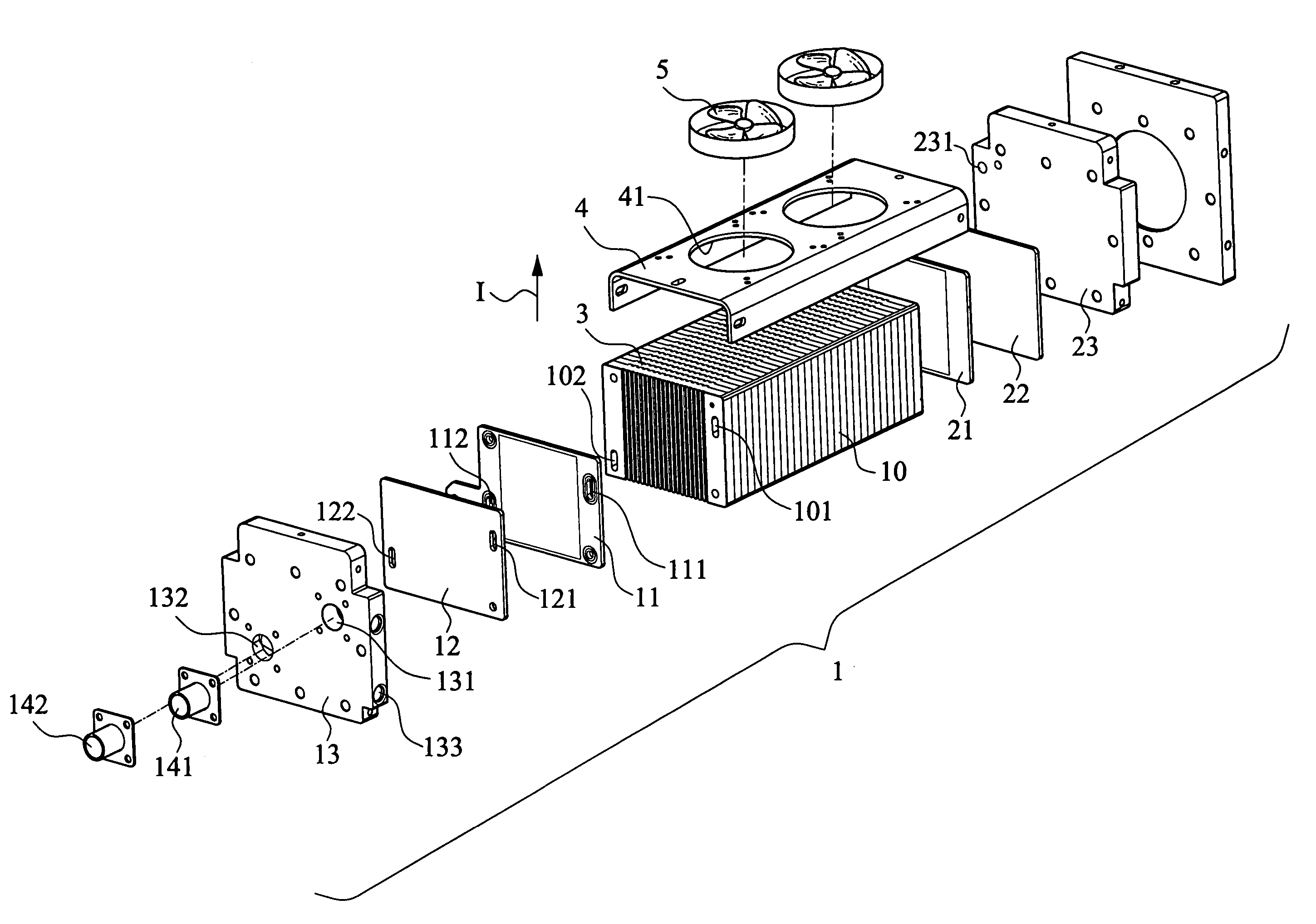
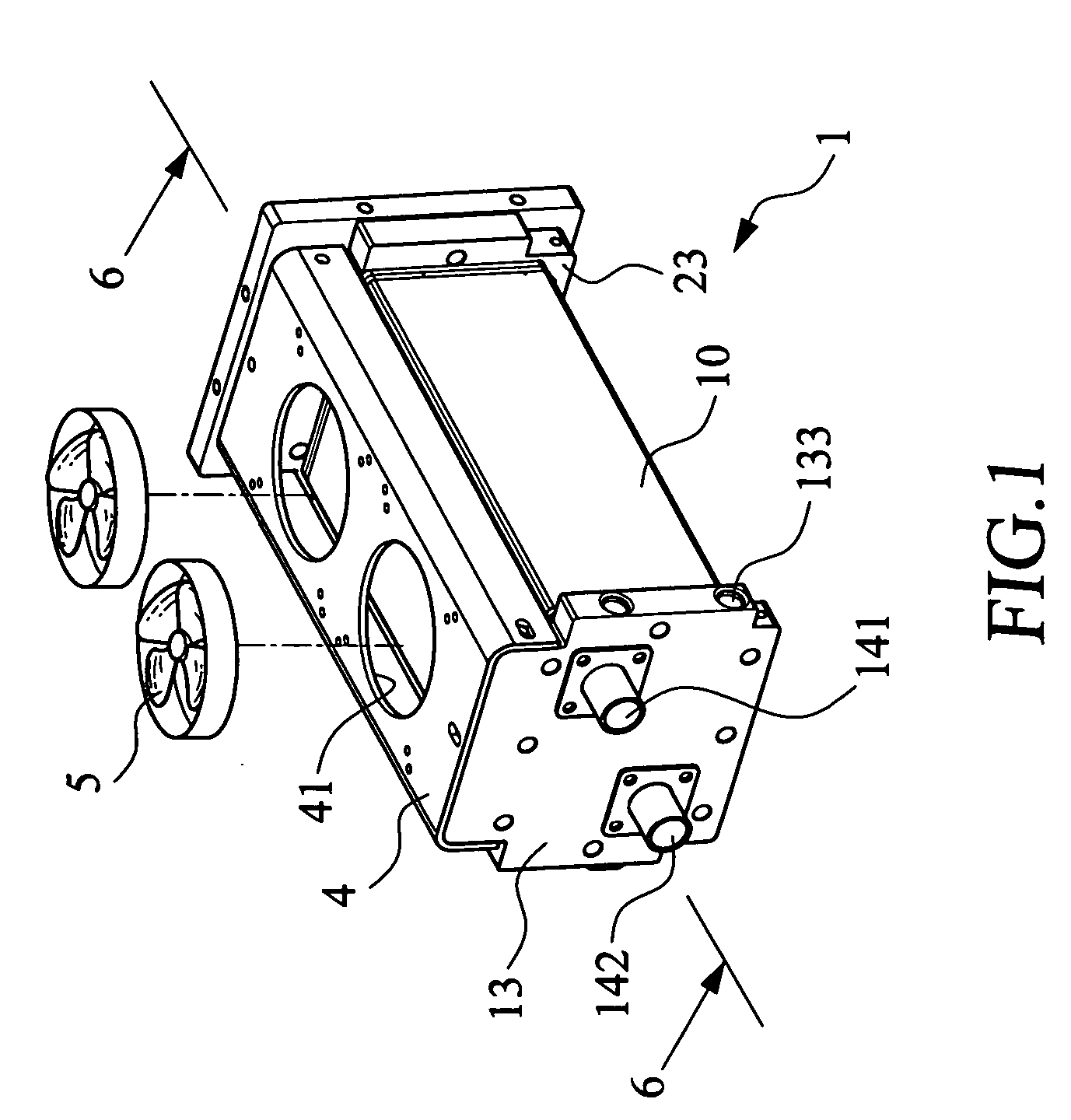
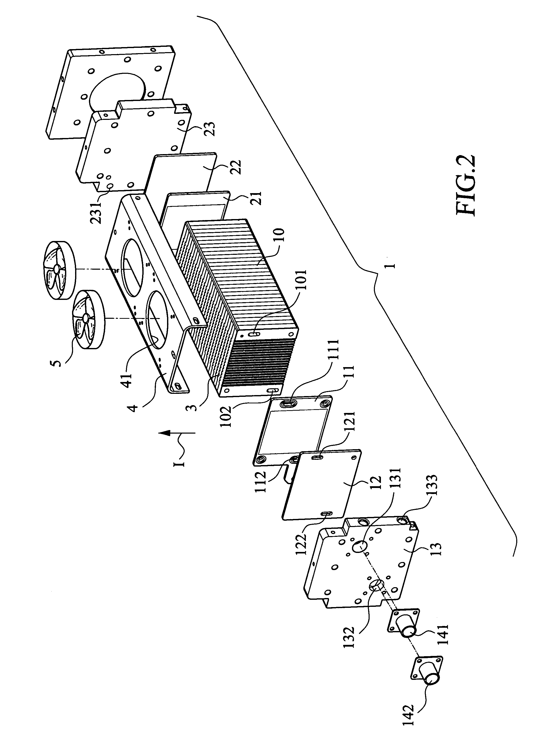
[0030] Please also refer to FIG. 6, which is a cross-sectional view of the fuel cell system 1 in accordance with the present invention. A fan casing 4 is mounted at a position close to the side of the air outlets A2 of the cooling air channels 3 formed in the fuel cell stack 10 of the fuel cell system 1. Two openings 41 are formed on the fan casing 4. Each of the openings 41 is mounted with a cooling air generating device, such as a fan 5 or a blower. When the fans 5 are turned on, they generate a cooling air flow in the cooling air channels 3 in a direction I. The cooling air travels from the cooling air inlet A1 into the cooling air channels 3 of the fuel cell stack 10 and comes out from the cooling air outlet A2. The cooling air removes heat and appropriately cools down the fuel cell stack 10.
[0031] Please refer to FIG. 7 which is a schematic plan view of the cooling air channels of the fuel cell stack. In order to generate a good cooling air flow, the cooling air inlet A1 is for...
second embodiment
[0032]FIG. 8 shows the air cooling system of the present invention. In this embodiment, the fuel cell system 1 further comprises a filter casing 61 and a filter 6 mounted to the openings of the filter casing 61. The filter casing 61 is arranged at a position close to the side of the cooling air inlet A1 of the cooling air channels 3 of the fuel cell stack 10. With the arrangement, the cooling air flows through the filter 6 before flowing into the cooling channels 3 and is filtered to remove dust and impurities.
third embodiment
[0033] Please refer to FIG. 9 which is a cross-sectional view of the present invention. As shown, the air cooling system is incorporated to the fuel cell system with a control device. The control device 7 may comprise a simple temperature controller. A temperature sensor 71 is provided in the fuel cell stack 10. The temperature sensor 71 may be provided at an appropriate position of the fuel cell stack 10, such as a position between two adjacent single cells. As shown in FIG. 5, the temperature sensor 71 is arranged at a position between the cathode plate 107a of the fuel cell unit 10a and the anode plate 105b of the fuel cell unit 10b. By means of the temperature sensor 71, the operation temperature of the fuel cell system 1 is detected.
[0034] Of course, the temperature sensor 71 may be disposed to any appropriate position for detecting the temperature of the fuel cell system 1. For example, the temperature sensor 71 may be mounted to a position close to the membrane electrode asse...
PUM
 Abstract
Description
Claims
Application Information
 - R&D
- Intellectual Property
- Life Sciences
- Materials
- Tech Scout
- Unparalleled Data Quality
- Higher Quality Content
- 60% Fewer Hallucinations
Browse by: Latest US Patents, China's latest patents, Technical Efficacy Thesaurus, Application Domain, Technology Topic, Popular Technical Reports.
© 2025 PatSnap. All rights reserved.Legal|Privacy policy|Modern Slavery Act Transparency Statement|Sitemap|About US| Contact US: help@patsnap.com