Device for metering a urea soulution

a technology of urea solution and metering device, which is applied in the direction of machines/engines, separation processes, instruments, etc., can solve the problem of relatively unproblematic measurement of state variables, and achieve the effect of accurate and selective determination of urea concentration

Inactive Publication Date: 2005-01-20
ROBERT BOSCH GMBH
View PDF12 Cites 47 Cited by
  • Summary
  • Abstract
  • Description
  • Claims
  • Application Information

AI Technical Summary

Benefits of technology

[0011] To improve the sensitivity of the measuring sensor the electrodes may be provided with a structure which increases their surface area. Such a surface area enlarging structure may be achieved, e.g., by a comb-shaped design of the electrodes, which additionally has the advantage that two electrodes designed in this way may be arranged to intermesh, so that a small distance between the two electrodes is adjustable simultaneously with a comparatively large surface area. Due to the large surface area, in particular in combination with the small distance, the test voltage and / or test current may be reduced and therefore the control and analyzing unit for a measuring sensor according to the present invention may be designed with small dimensions. A separate electrode may be provided for simultaneous determination of multiple state variables, if necessary. For example, by using such a third electrode, it is possible to determine the pH, while another state variable, e.g., the dielectric constant, is determined using the two aforementioned electrodes.
[0016] In an exemplary embodiment, a sensor unit is provided with a measuring sensor for an electric state variable and with a measuring sensor for a physicomechanical state variable. The measured values of the two measuring sensors are used in an analyzer unit to determine the urea concentration in solution. By analyzing two independent state variables, this yields the possibility of a more accurate and more selective determination of the urea concentration.

Problems solved by technology

Measurement of these state variables is comparatively unproblematical and in particular it is possible to perform these measurements in situations of extreme temperature variations.

Method used


Image

  • Device for metering a urea soulution
  • Device for metering a urea soulution

Examples


Embodiment Construction

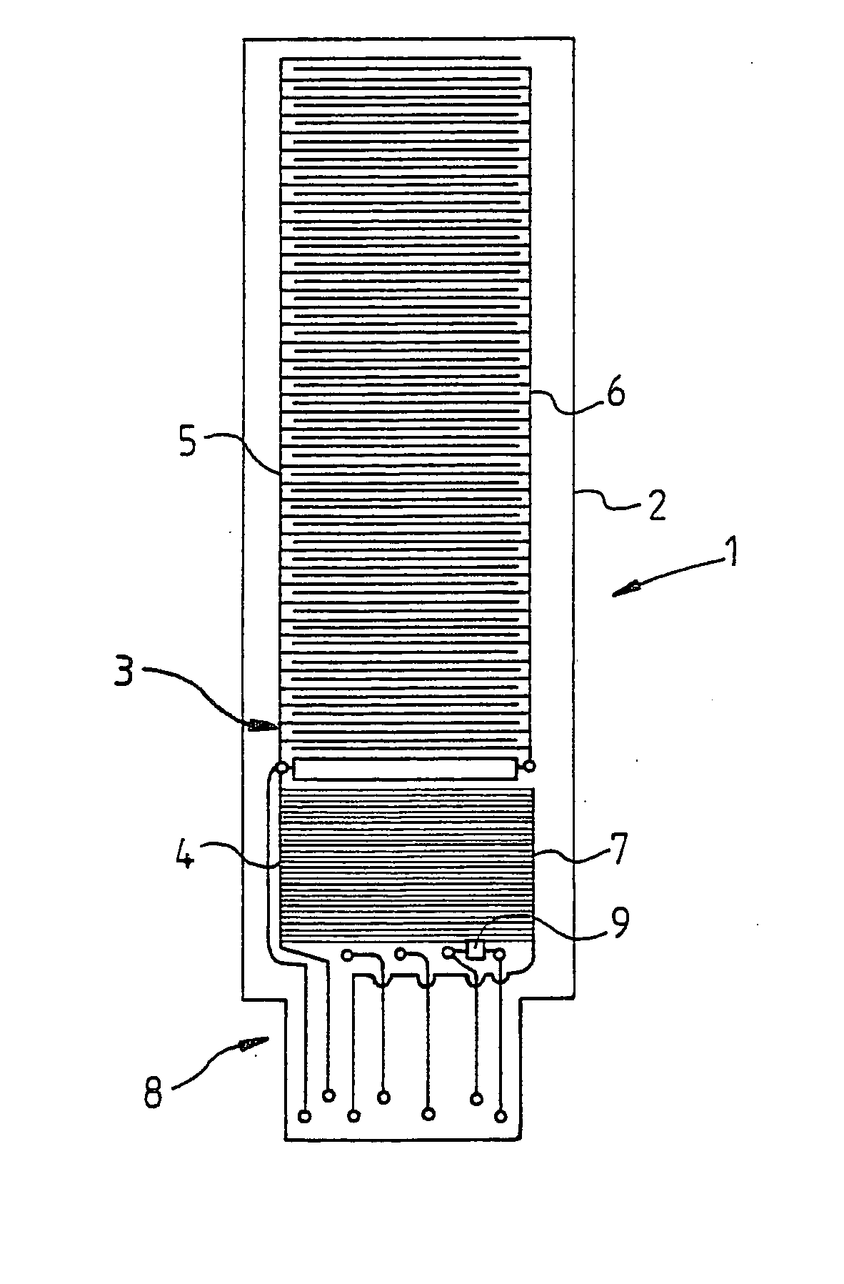
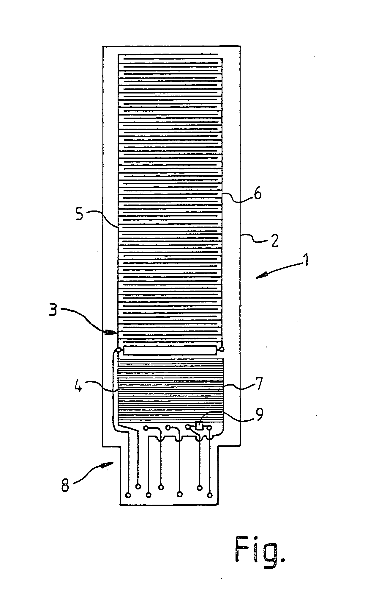
[0022] Sensor unit 1 is mounted on a sensor plate 2. A comb-shaped electrode 3 is divided into two areas 4, 5. Individual teeth of the comb structure are spaced farther apart in upper area 5 than in lower area 4. In upper area 5, another electrode 6 engages with a corresponding comb structure. The two electrodes 5 and 6 extend over a large area of sensor plate 2 and constitute a filling level sensor. A third electrode 7 is situated opposite lower area 4 of electrode 3. The comb structure of electrode 7 corresponds to the finer comb structure of lower area 4 of electrode 3, i.e., the teeth are not as far apart.

[0023] Together with lower area 4 of electrode 3, electrode 7 forms a measuring sensor according to an exemplary embodiment of the present invention for measuring an electric state variable, e.g., the conductivity, the dielectric constant, etc.

[0024] Electric terminals 8 for electrodes 3, 6, 7 are provided in the lower area of sensor plate 2. These electric terminals 8 may be...


PUM

PropertyMeasurementUnit
physical stateaaaaaaaaaa
electric stateaaaaaaaaaa
dielectric constantaaaaaaaaaa

Abstract

A device for metering urea solutions permitting a reliable reduction of nitrogen oxides in the exhaust gas of an internal combustion engine is provided. This is achieved by the fact that the device for metering the urea solution includes a sensor unit for monitoring one or more physical state variables of an enzyme-free Urea solution.

Description

FIELD OF THE INVENTION [0001] The present invention relates to a device for metering a urea solution. BACKGROUND INFORMATION [0002] To reduce nitrogen oxides in the exhaust gas of motor vehicles, urea solution has in the past been sprayed into the exhaust gas during catalytic reduction. Urea is broken down into carbon dioxide and ammonia by chemical reaction on a hydrolysis catalyst. Ammonia then reacts selectively with nitrogen oxides to form nitrogen and water, thus removing nitrogen oxides from the exhaust gas. [0003] For reliable reduction of nitrogen oxides with a urea solution, various parameters are important, in particular the urea concentration in the aqueous solution. [0004] Sensor applications known in the past for measuring the urea concentration in the fields of medicine and biology have used urease, which enzymatically and selectively breaks down urea to form ammonia. Sensors then detect the influence of the ammonia on the pH of the solution. Information regarding the ...

Claims


Application Information

Patent Timeline
Patent Type & Authority Applications(United States)
IPC IPC(8): G01N11/16B01D53/90B01D53/94F01N3/08F01N3/20G01N5/02G01N27/06G01N27/10G01N27/22G01N27/416
CPCB01D53/90B01D53/9495F01N3/2066F01N11/00F01N2610/02Y02T10/24F01N2900/1814F01N2900/1818G01N33/0009Y02T10/47F01N2900/1811Y02T10/12Y02T10/40
Inventor RIPPER, WOLFGANGBERGER, JOACHIMMAHR, BERNDBRINZ, THOMAS
Owner ROBERT BOSCH GMBH
Why Eureka
Try Eureka