Digital multiphase control system

a control system and digital technology, applied in power conversion systems, dc-dc conversion, dc source parallel operation, etc., can solve the problems of excessive heat produced by drivers, power supplies for computing and telecom applications continue to be challenged, etc., and achieve the effect of increasing the instruction set and high performan

Inactive Publication Date: 2005-01-20
INTERNATIONAL RECTIFIER COEP
View PDF5 Cites 41 Cited by
  • Summary
  • Abstract
  • Description
  • Claims
  • Application Information

AI Technical Summary

Benefits of technology

[0007] In accordance with the present invention, a controller generates a digital instruction set that communicates to the phases through a bus system that is connected in parallel to all the phase drivers. The bus system is straight forward and can accommodate enough instructions to control the power supply for high performance. Instructions can be added by increasing the number of digital bus lines. However, creating longer pulses or multiple pulses in predetermined patters with corresponding logic to decode the information are other ways of communication, which can be used to increase the instruction set without additional bus lines. Further, with appropriate logic in the phase driver the invention can also be implemented with fewer bus lines. Although a system can be devised with a single bus line, a two-line bus system is preferred as the minimum number of lines necessary to gain practical control of the power converter. In the two line system, one line is used to turn a phase ON and another line is used to turn a phase OFF, which allows for simultaneity of these commands.

Problems solved by technology

Power supplies for computing and telecom applications continue to be challenged to supply higher current as system voltages drop.
However, as the number of phases increases, heat produced by the drivers becomes excessive, indicating the desirability to transition to the use of external drivers.

Method used


Image

  • Digital multiphase control system
  • Digital multiphase control system
  • Digital multiphase control system

Examples


Embodiment Construction

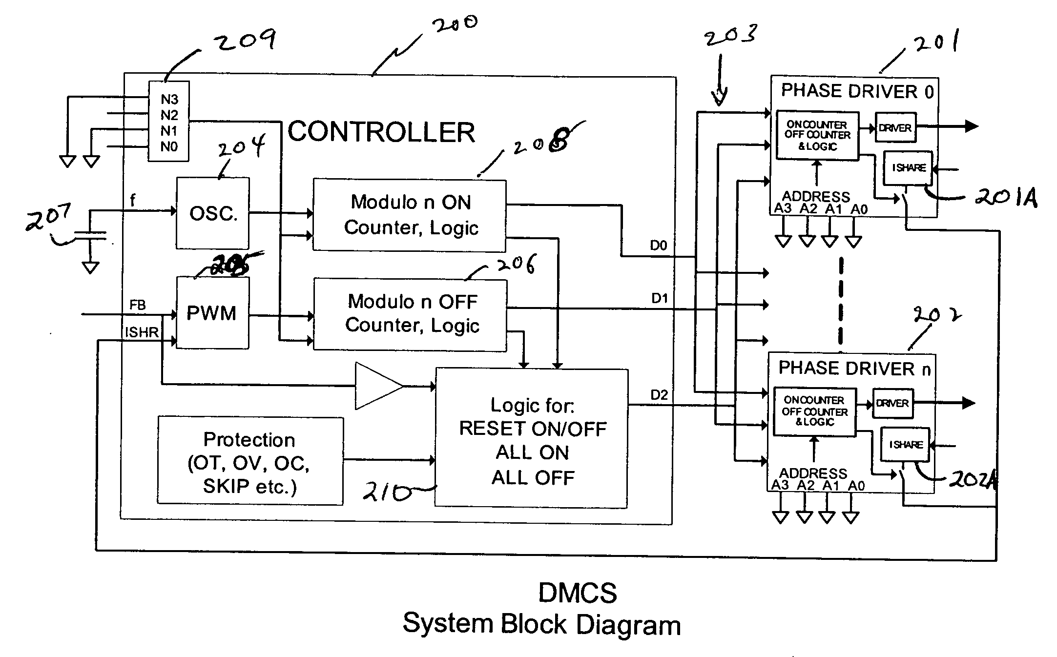
[0027] Referring first to FIG. 1, there is shown a controller 200 and a plurality of individual phase drivers 201, 202, which represent the first and last of n drivers. FIG. 1 illustrates the invention for a 3-wire digital bus configuration 203.

[0028] The main controller 200 contains an oscillator 204 and a pulse width modulator 205 as common components to an analog control IC. A suitable passive component fixes the frequency f of the oscillator 204. Oscillator 204 is connected to the ON counter logic 205 and the modulator 205 is connected to the OFF counter logic 206.

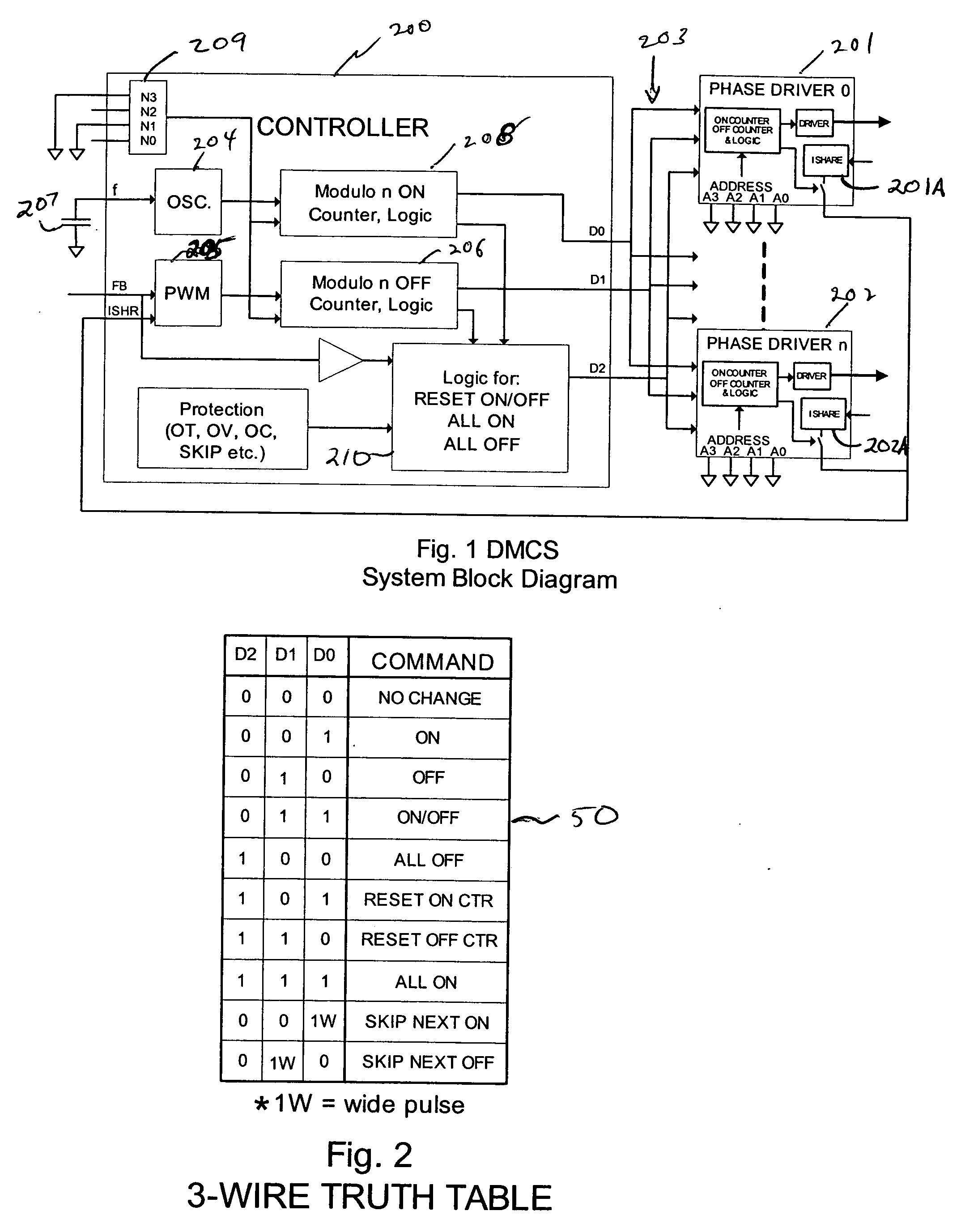
[0029] Controller 200 generates a digital instruction set that communicates to phase drivers zero through N (201, 202). A bus 203 provides the channel for communication between controller 200 and phase drivers 201, 202. Controller 200 generates a digital instruction set that communicates with phase drivers 201, 202 through a bus system 203 that is connected in parallel to each of the phase drivers. Bus 203 is configu...


PUM


Abstract

A multi-phase control system for a power supply provides a data bus between a controller and multiple phase drivers to obtain a synchronous control through a flexible and non-dependent control configuration. The controller provides data signals to the data bus that is connected to the various phase drivers, with the data signals dependent upon a switching frequency and ON/OFF command signals for a particular phase. Each of the phase drivers have decoding logic for receiving the data signals over the data bus, as well as independent selection or addressing logic for choosing the phase driver to react to the data signals on the data bus. A variety of control configurations may be realized according to this control technique including resetting all drivers, setting all phases to ON or all phases to OFF conditions, skipping phase activation and so forth. The flexible control permits output current sharing to be controlled among the various phases to provide a desired output current for the power supply. The control configuration permits fast and robust response to transient conditions while providing a simplified control in an N phase system over a data bus that can vary between 1 and M lines.

Description

RELATED APPLICATION [0001] This application claims the benefit of U.S. Provisional Application No. 60 / 487,294, filed Jul. 14, 2003. This application is related to application Ser. No. 10 / 392,121 filed Mar. 18, 2003 the subject matter of which is incorporated herein by reference.FIELD OF THE INVENTION [0002] This invention relates to power supplies and more specifically relates to a novel multi phase topology power supply with a digital implementation. BACKGROUND OF THE INVENTION [0003] Power supplies for computing and telecom applications continue to be challenged to supply higher current as system voltages drop. Accordingly, power supplies have gone from single phase to multiple phase topologies. To produce a single output voltage in a multi phase design, several power stages, or phases, are paralleled together such that the current from each phase is summed to produce the desired output current. For n stages in parallel, one of the phases will start its period every 360 / n electric...

Claims


Application Information

Patent Timeline
Patent Type & Authority Applications(United States)
IPC IPC(8): H02J1/10H02M3/157H02M3/158
CPCH02J1/102H02M3/1584H02M3/157
Inventor MIHALKA, ALEX
Owner INTERNATIONAL RECTIFIER COEP
Why Eureka
Try Eureka