Liquid chromatograph and analysis system

a liquid chromatograph and analysis system technology, applied in the field of liquid chromatographs, can solve the problems of difficult operation of hplc, difficult to confirm whether the flow is flowing, and the gradient elution cannot be hardly performed at high precision, so as to achieve the effect of effective separation and detection within a short time, high sensitivity, and prolonging the elapsed time for detection

Inactive Publication Date: 2005-01-27
NANO SOLUTION
View PDF20 Cites 10 Cited by
  • Summary
  • Abstract
  • Description
  • Claims
  • Application Information

AI Technical Summary

Benefits of technology

[0016] This means permits a free selection of either of a stepwise elution method in which the composition of an eluent is changed stepwisely or a gradient elution method in which the composition of an eluent is changed continuously. Therefore, it becomes possible to effectively separate and detect within a short time at a low flow rate even in the case of a multiple-component sample that has been difficult to elute by an eluent having a single composition.
[0017] The analysis system of the present invention comprises a liquid chromatograph constructed such that the gradient elution of a solute can be performed by feeding a small flow volume of the eluent at a low flow rate, so that the detection of a solute component can be performed at high sensitivity, while more extending an elapsed time for the detection.
[0018] As a result, a mass spectrometry with high sensitivity can be performed because of allowing a more increase in concentration of the peak of the sample separation data obtained by the mass spectrometer.

Problems solved by technology

However, the HPLC designed for low flow rate had a very complicated device structure, so that there was a basic technical problem in that the operation of the HPLC was difficult.
However, this technology had technical problems in that a gradient elution can be hardly performed at high precision because the subsidary stream tended to be clogged, the desired low flow rate condition of the predetermined (Sub-uL / min) was hardly kept in stable, and it became difficult to confirm whether the flowing was occurred at a predetermined flow rate.

Method used


Image

  • Liquid chromatograph and analysis system
  • Liquid chromatograph and analysis system
  • Liquid chromatograph and analysis system

Examples


example 1

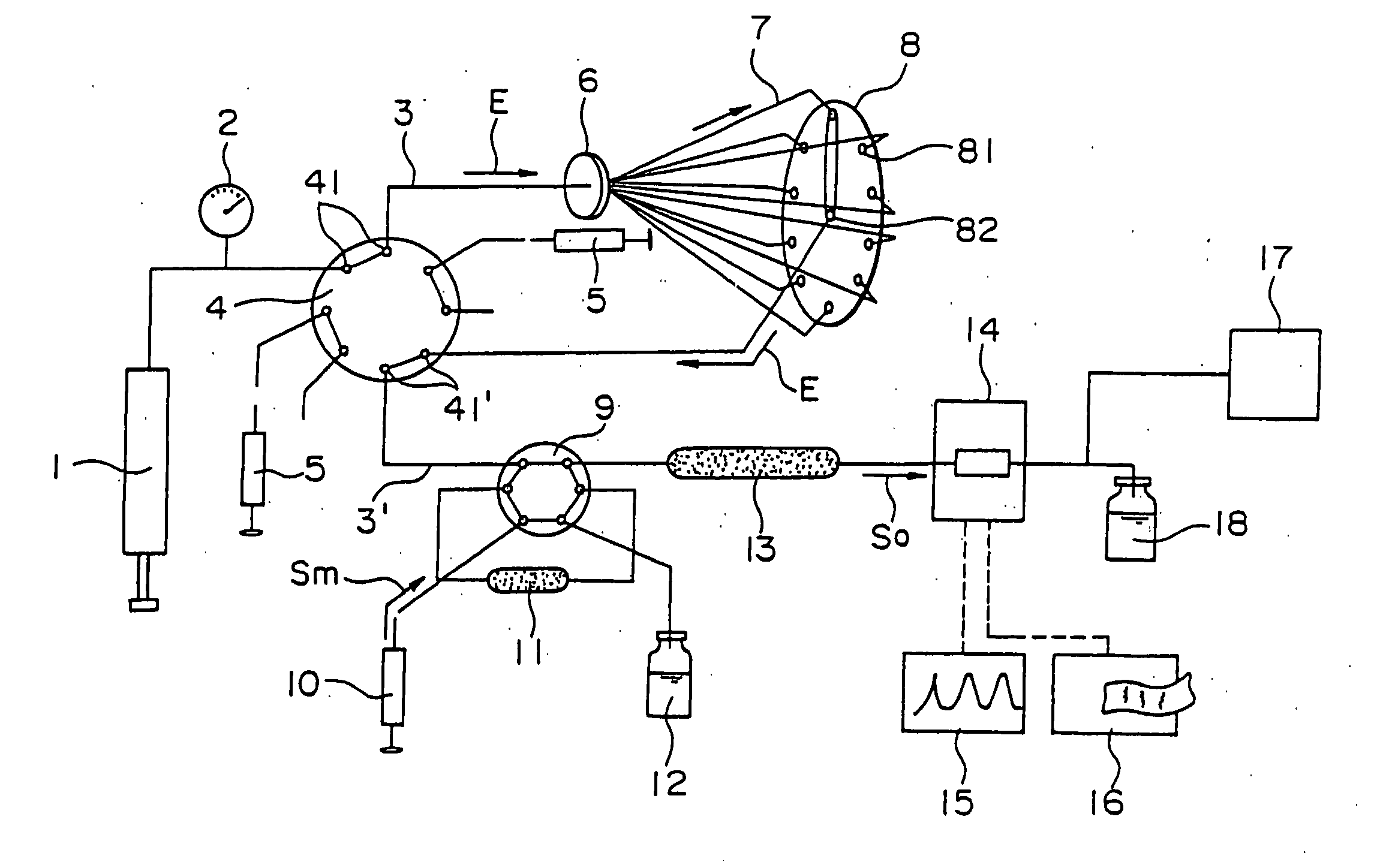
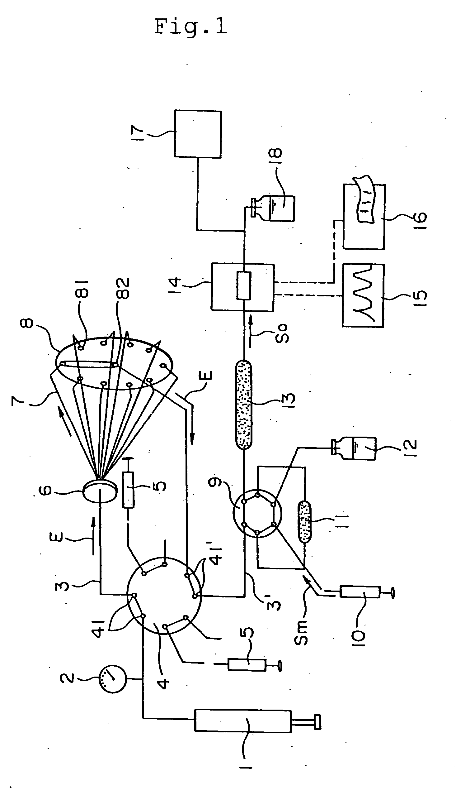
[0049] A methanol solution of acetone was used as an eluent and the gradient change when the concentration of acetone in the methanol was changed by 10% was investigated using a UV detector at each of flow rates of 500 nL / min, 300 nL / min, and 100 nL / min.

[0050] In this experiment, the trap column 11, the separation column 13, and a mixing device were not used.

[0051]FIG. 3 is a diagram (graph) that shows a base line drawn by the recorder 15 in Example 2. As shown in this gradient line, a stable gradient change is shown at each of the flow rates of 500 nL / min, 300 nL / min, and 100 nL / min. In particular, even at a low flow rate of 100 nL / min, a linear base line can be formed and thus it is enough to attain a linear gradient change of the eluent.

example 2

[0052] Using a mixing device, a methanol solution of acetone was used as an eluent and the gradient change when the concentration of acetone in the methanol was changed was investigated using a UV detector at each of flow rates of 300 nL / min and 100 nL / min.

[0053]FIG. 4 is a diagram (graph) that shows a base line drawn by he recorder 15 in Example 3. As shown in this gradient line, a stable gradient change is shown at each of the flow rates of 300 nL / min and 100 nL / min. In particular, even at a low flow rate of 100 nL / min, a linear base line can be formed and thus it is enough to attain a linear gradient change of the eluent.

example 3

[0054] An experiment was carried out in order to prove that the analysis system of the present invention permits a high sensitive analysis of a peptide.

[0055] The sample used was a product of digesting calmodulin with the enzyme trypsin (a calmodulin trypsic digest) and the amount thereof was 150 fmoles.

[0056] The eluent used was one that comprises water, acetonitrile, and formic acid. The injection amount of the sample was 60 nL. The sample was directly introduced into a separation column. The flow rate was 300 nL / min. Furthermore, the range of molecular weight measured by a mass spectrometer was in the range of 600 to 1,500 Daltons.

[0057]FIG. 5 is a diagram (a graph) shows a chromatograph of each mass component contained in the calmodulin trypsic digest. As various kinds of mass components form the respective sharp peaks, so that the separation of each sample component can be clearly found.

[0058]FIG. 6 is a diagram (a chromatograph) showing the results in which a peptide with ...


PUM

PropertyMeasurementUnit
flow rateaaaaaaaaaa
diameteraaaaaaaaaa
volumeaaaaaaaaaa

Abstract

The present invention aims to provide a liquid chromatograph, an analysis system, and a gradient elution method, which are designed to permit a gradient change of eluent with higher precision and also permit a high sensitive detection or analysis. For attaining the object, there are provided: a liquid chromatograph having at least a liquid-feeding means 1 for flowing an eluent E at a predetermined flow rate, a sample-pouring means 9 for pouring a sample Sm into the eluent E, and a separation-column means 13 for separating a solute So contained in the sample Sm into components, comprising an eluent-selecting means 8 for forming branched flow paths 7 having predetermined volumes by dividing a flow path 3 of the eluent E fed from the liquid-feeding means 1, temporally storing eluents E1, E2, and soon in the branched flow paths 7, and pouring the sample Sm into the selected eluents E1, E2, and so on, and means for carrying out a gradient elution of a solute So; an analysis system comprising a mass spectrometer connected to the liquid chromatograph, and a gradient-elution method using the liquid chromatograph.

Description

TECHNICAL FIELD [0001] The present invention relates to a liquid chromatograph suitable for analysis on gradient elution, an analysis system having such a liquid chromatograph, and a method of gradient elution using the liquid chromatograph. BACKGROUND ART [0002] There is an analysis technique that utilizes the so-called gradient elution method (a gradient elution technique) in which the composition (the constituent ratio) of an elute is sequentially changed and then flowed into a separation column using a high-performance liquid chromatograph (hereinafter, referred to as “HPLC”) to change the elution strength of a solute kept in the separation column. [0003] This analysis technique has been widely applied because of its advantages in that a separation requiring a great elution time can be completed within a short time, a separation between molecules having similar structures can be allowed, and so on. [0004] In this analysis technique, currently, it is general to feed the eluent at...

Claims


Application Information

Patent Timeline
Patent Type & Authority Applications(United States)
IPC IPC(8): G01N27/62G01N30/26G01N30/34G01N30/72
CPCG01N30/34G01N30/7233G01N2030/8411
Inventor YAMAUCHI, YOSHIONATSUME, TOHRUISOBE, TOSHIAKI
Owner NANO SOLUTION
Why Eureka
Try Eureka