Catalytic burning reaction

Active Publication Date: 2005-01-27
BOSTEELS DOMINIQUE
View PDF10 Cites 58 Cited by
  • Summary
  • Abstract
  • Description
  • Claims
  • Application Information

AI Technical Summary

Benefits of technology

[0023] The catalyst of the invention enables a down sizing of the motor or engine with respect to a motor not provided with the catalyst of the invention, without loss of energy o

Problems solved by technology

This catalyst had however the drawback to require the use of a costly noble metal, e.g. palladium.
Due to said deposit, the efficiency of the converter is reduced.
Such a regeneration is a loss of energy, as said energy is wasted for the working of the motor.
As stated in said document, problems of combustion catalyst are t

Method used


Image

  • Catalytic burning reaction
  • Catalytic burning reaction
  • Catalytic burning reaction

Examples


examples

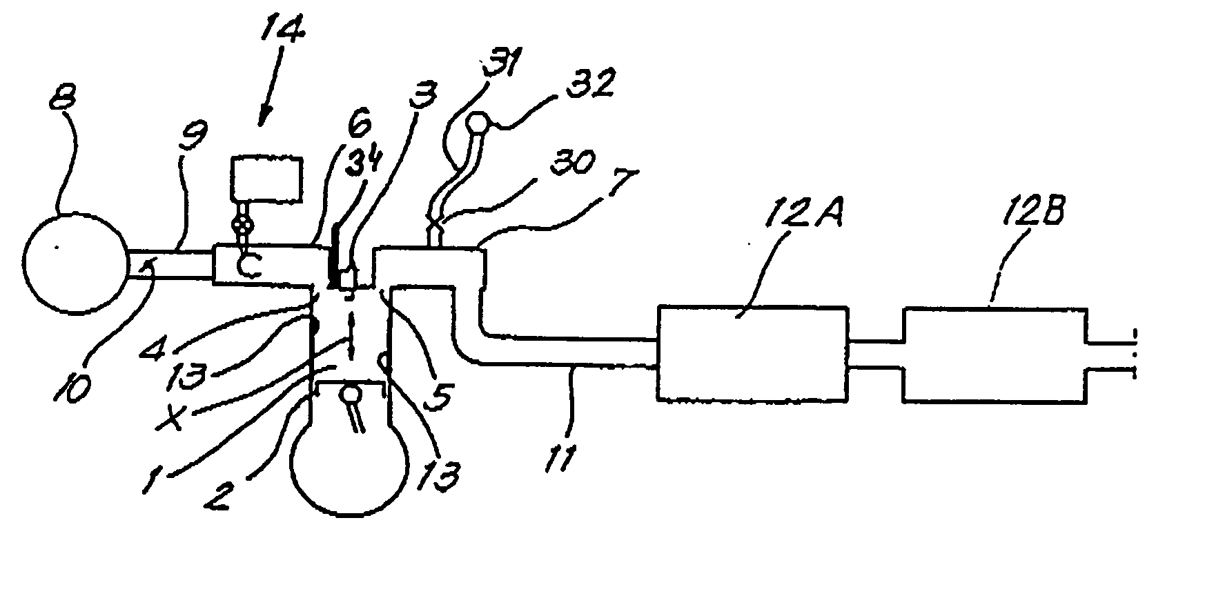
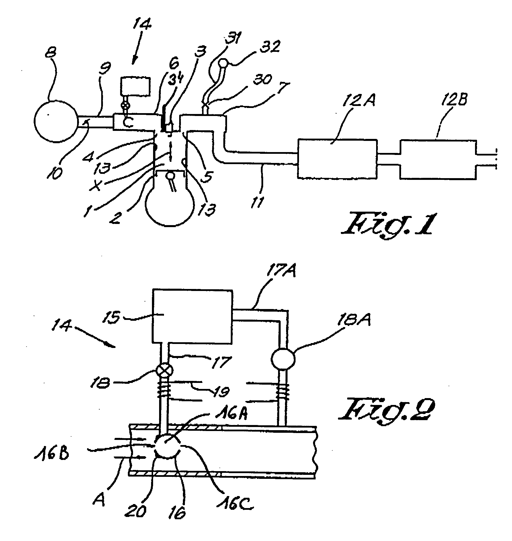
[0197] The motor of FIG. 1 comprises several chambers 1 in each of which a piston 2 is moved (arrow X). A spark plug 3 is used for the ignition of the mixture air-fuel present in the chamber 1. Valves 4,5 are actuated so as to allow the inlet of air and combustible in the chamber 2, the outlet of flue gases out of the chamber 2, as well as a possible flushing effect (the inlet valve or valves and the outlet valve or valves being in open position, whereby enabling air to cool the chamber and to remove some still present flue gases) as well as a cooling effect of the flue gases. The motor comprises also: an intake manifold 6, an outlet manifold 7, an air filter 8, a pipe 9 with possibly a valve or butterfly 10 for controlling the air or air-fuel consumption, an outlet pipe 11, a filtering system 12A for the flue gases (for example for further oxidizing thereof, for trapping particles, 3-ways catalyst system, etc) and a soot trap system 12B. The engine of FIG. 1 is a four stroke engine...


PUM

PropertyMeasurementUnit
Temperatureaaaaaaaaaa

Abstract

Catalytic system combining an aluminium or iron containing catalytic support, a rare earth containing porous deposit, carbon nanoparticles and a carbon containing structure making bonds between carbon nanoparticles.

Description

[0001] The present application is a Continuation in Part (CIP) of U.S. Ser. No. 10 / 268,629 filed on Oct. 10, 2002 and claiming the priority of provisional application U.S. Ser. No. 60 / 328,352 filed on Oct. 10, 2001, as well as a continuation in part of PCT / BE03 / 00170 filed on Oct. 9, 2003 and claiming the priority of PCT / BE02 / 00156 filed on Oct. 10, 2002.PRIOR ART [0002] It has already been proposed to use specific catalytic system or converter for treating exhaust combustion gases for reducing the NOx and / or CO and / or HC and / or soot content of said exhaust combustion gases. Such system requires different specific catalysts or catalytic systems for each purposes. [0003] For example, the three-way catalysts used in the exhaust system of cars comprise platinum and rhodium in different layers. A structural catalyst system using only Pd was developed, said system comprising a base layer of palladium on cerium dioxide, said base layer being covered with an upper layer containing palladiu...

Claims


Application Information

Patent Timeline
IPC IPC(8): B01D53/94F01N3/035F01N3/28F01N13/00F02B1/12F02B51/02F23C13/00
CPCB01D53/9431Y10T428/25B01J21/18B01J23/10B01J37/08B82Y30/00F01N3/035F01N3/2803F01N2340/02F01N2510/06F01N2570/14F02B1/12F02B51/02F02B77/02F23C13/00Y02T10/126Y02T10/22F01N13/009Y10T428/265Y10T428/12535Y10T428/30B01D53/945Y02T10/12
Inventor BOSTEELS, DOMINIQUE
Owner BOSTEELS DOMINIQUE
Why Eureka
Try Eureka