Eureka AIR delivers breakthrough ideas for toughest innovation challenges, trusted by R&D personnel around the world.

Method and apparatus for cleaning and method and apparatus for etching

Inactive Publication Date: 2005-01-27
LAIR LIQUIDE SA POUR LETUDE & LEXPLOITATION DES PROCEDES GEORGES CLAUDE
View PDF3 Cites 358 Cited by
  • Summary
  • Abstract
  • Description
  • Claims
  • Application Information

AI Technical Summary

Benefits of technology

[0006] This invention was developed in view of the problems described above for the prior art. The object of this invention is to provide improvements in the safety, cost, and flexibility of the IFCG-based cleaning methods and apparatuses and IFCG-based etching methods and apparatuses that are used in semiconductor processing systems.
[0017] According to a sixth aspect of this invention, the upstream section in the apparatus of the fifth aspect is provided with a controller that can vary the first halogen gas:fluorine gas:inert gas volumetric ratio in the aforesaid mixed gas through independent adjustment of the individual flow rates of the first halogen gas, fluorine gas, and inert gas.

Problems solved by technology

However, CIF3 is very corrosive and strongly oxidizing and in particular has a very high reactivity in its liquid phase.
This places limitations from a materials standpoint on the ability to heat the pumps and conduits, while at the same time heating the pumps and conduits is also undesirable from a practical standpoint.
In addition, the storage and transport of this highly reactive liquefied CIF3 gas is tightly regulated in the United States and Europe, which places limitations on its range of applications notwithstanding the fact that it is a highly desirable cleaning gas.
In another vein, since very high purity levels are not required when CIF3 is used as a cleaning gas, instances occur in which the CIF3 purity required by the user does not match the cost of CIF3 production.

Method used


Image

  • Method and apparatus for cleaning and method and apparatus for etching
  • Method and apparatus for cleaning and method and apparatus for etching
  • Method and apparatus for cleaning and method and apparatus for etching

Examples


Embodiment Construction

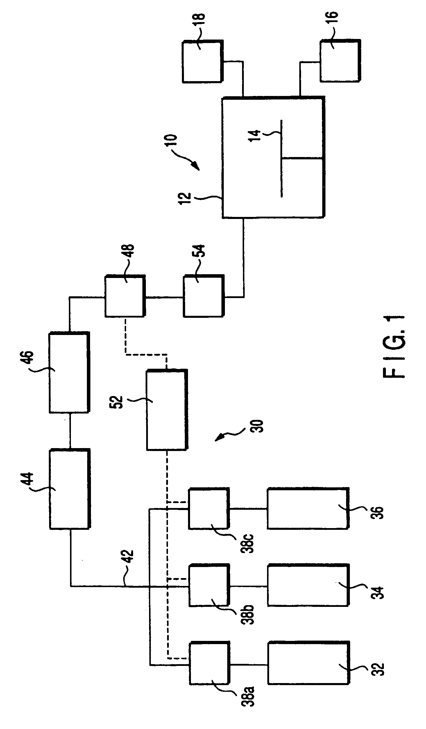
[0032]FIG. 1 contains a schematic drawing of a cleaning apparatus that is an embodiment of this invention and that removes by-product that has accumulated within the treating chamber of a semiconductor processing system. This cleaning apparatus 30 may be connected to, for example, a CVD apparatus 10 set up to form a silicon film on a treatment substrate, e.g., a semiconductor wafer or LCD substrate.

[0033] The CVD apparatus 10 is provided with a treating chamber 12 that holds the treatment substrate. Disposed within the treating chamber 12 is a platform 14 for mounting the treatment substrate. The lower region of the treating chamber 12 is connected to an exhaust system 16 that exhausts the interior and establishes a vacuum therein. The upper region of the treating chamber 12 is connected to a feed system 18 that supplies process gas, for example, SiH4.

[0034] The repetition of film-forming processes in such a CVD apparatus 10 causes the accumulation of by-product (main component=Si...


PUM

PropertyMeasurementUnit
Temperatureaaaaaaaaaa
Fractionaaaaaaaaaa

Abstract

A cleaning apparatus (30) is connected to a treating chamber (12) of a CVD apparatus (10) for forming a silicon film. The cleaning apparatus (30) has a first, a second, and a third gas sources (32, 34, 36) and a chlorine gas, a fluorine gas, and an inert gas are introduced from the gas sources through FMC (38a, 38b, 38c), respectively, with flow rates controlled independently from one another. Those gases are gathered at a pipe (42) and mixed into a mixed gas. The mixed gas is passed through a heated reactor (44) such as a heat exchanger to thereby react the chlorine gas with the fluorine gas and form a formed gas containing fluorinated chlorine gas such as CIF3. The formed gas is supplied to the treating chamber (12) through a cooler (46), an analyzer (48) and a buffer (54).

Description

TECHNICAL FIELD [0001] This invention relates to a cleaning method and apparatus and an etching method and apparatus for semiconductor processing systems wherein said cleaning method and apparatus and said etching method and apparatus use an interhalogen fluorine compound gas (IFCG). Here, semiconductor processing denotes the various processes that are executed in order to fabricate a semiconductor device—or a structure that connects to a semiconductor device—on a treatment substrate through the formation thereon of a semiconductor layer, insulating layer, conductive layer, etc., in a prescribed pattern. Said treatment substrate can be, for example, a semiconductor wafer or an LCD substrate, and the connecting structure can be, for example, a conductor, trace, or electrode. BACKGROUND ART [0002] Interhalogen fluorine compound gases, such as CIF3, are used in semiconductor processing systems to etch treatment substrates and to clean the treating chambers and exhaust pipe systems. For...

Claims


Application Information

Patent Timeline
IPC IPC(8): C23C16/44C23C16/448H01L21/00
CPCB08B7/0035H01L21/67063C23C16/4488C23C16/4405
Inventor SONOBE, JUNKORUDA, YOSHIKUNIZILS, REGISINO, MINORUKIMURA, TAKAKONISHIKAWA, YUKINOBU
Owner LAIR LIQUIDE SA POUR LETUDE & LEXPLOITATION DES PROCEDES GEORGES CLAUDE
Why Eureka
Eureka Blog
Learn More