Mass spectrometer

a mass spectrometer and mass technology, applied in the field of mass spectrometers, can solve the problems of not being applied to the application field requiring high mass accuracy, reducing sensitivity, and achieving high mass accuracy. , the effect of high mass accuracy and msn (n3) analysis

Active Publication Date: 2005-02-03
HITACHI HIGH-TECH CORP
View PDF7 Cites 26 Cited by
  • Summary
  • Abstract
  • Description
  • Claims
  • Application Information

AI Technical Summary

Benefits of technology

[0016] The present invention intends to provide a mass spectrometer capab...

Problems solved by technology

The methods of the prior arts 1, 2, and 3 involve a problem that the mass accuracy obtainable is only about 10 ppm to 100 ppm by the chemical mass shift caused by collision against a buffer gas upon ion detection and space charges caused by coulombic repulsion between ions to each other and it can not be applied to the application field requiring high mass accuracy.
The ion ejection time from the linear trap region to the time-of-flight mass spectrometer lowers the ion duty efficiency (duty cycle) and, thus, lowers the sensitivity since other measurement is interrupted during the ion ejection.
Use of a high ejection potential results in a problem of increasing the divergency of energy in the directio...

Method used


Image

  • Mass spectrometer
  • Mass spectrometer
  • Mass spectrometer

Examples


first embodiment

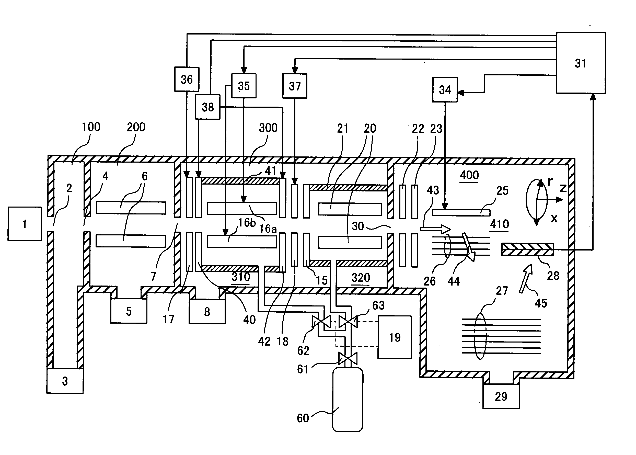
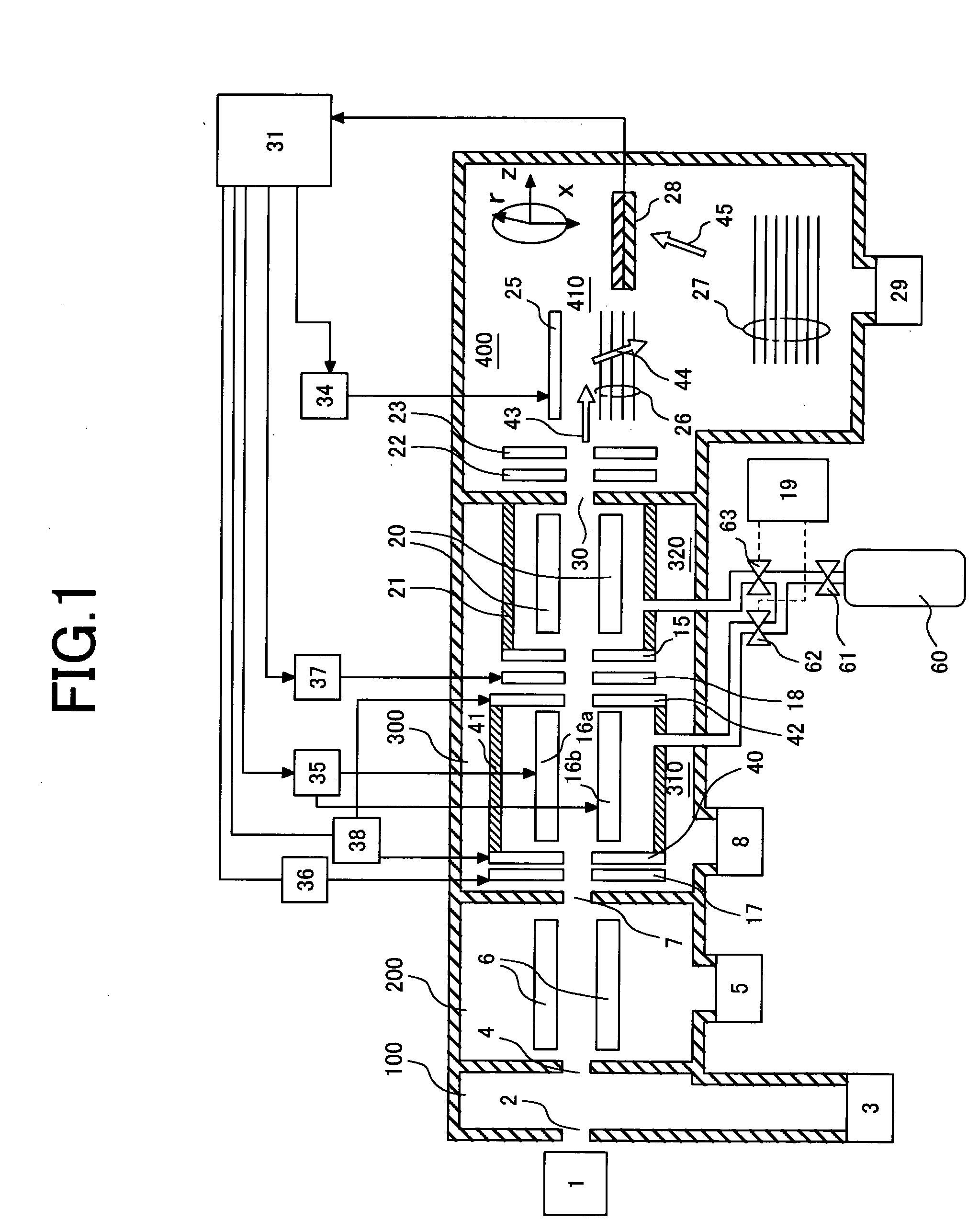
[0038]FIG. 1 is a conceptual view showing the constitution of a time-of-flight mass spectrometer in an atmospheric pressure ionization / quadrupole linear trap applied with the present invention in a state cross sectioned at a central portion.

[0039] Reference numeral 1 denotes an atmospheric ionization source, for example, an electrospray ionization source, an atmospheric pressure chemical ionization source, an atmospheric pressure photoionization source, or an atmospheric pressure matrix assisted laser desorption ionization source. Ions generated from the atmospheric pressure ionization source 1 are passed through an orifice 2 and introduced to a first differential pumping region 100 pumped by a rotary vacuum pump 3. The pressure of the first differential pumping region is about at 100 to 500 Pa.

[0040] Then, the ions are passed through an orifice 4 and introduced to a second differential pumping region 200 pumped by a turbo molecular pump 5. In the region, the pressure is kept at a...

second embodiment

[0069]FIG. 12 is a conceptual view showing the constitution of a time-of-flight mass spectrometer a matrix assisted laser desorption ionization quadrupole in linear trap applied with the present invention in a state cross sectioned at a central portion. As can be seen easily in comparison with FIG. 1, while a sample is ionized under an atmospheric pressure and introduced to a mass spectrometer in the first embodiment, a sample is ionized by an ionization chamber 50 at a pressure of about 0.05 to 5 Pa in the second embodiment, different from the first embodiment. The ionization chamber 50 is exhausted by a turbo-molecular pump 5 and maintained at a pressure of about 0.05 to 5 Pa. In the ionization chamber 50, a sample plate 53 is located. The sample plate 53 has a sample surface on which a sample solution formed by dissolving an ionized sample and a matrix solution mixed therewith is dripped and dried. The ionization chamber 50 has orifices 56 and 57. With respect to the orifice 56, ...


PUM


Abstract

An ion mass spectrometer comprising an ionization source for generating ions, a linear trap region for accumulation and dissociation of ions, and a time-of-flight mass spectrometer for mass spectroscopy of ions based on the flying time, and having a collision damping region introduced with a buffer gas for reducing the kinetic energy of ions ejected from the linear trap region and converting the ion packet into continuous beam and provided with plural electrodes for generating multipole electric fields in the inside between the linear trap region and the time-of-flight mass spectrometer, and having an ion transmission control mechanism for allowing or inhibiting incidence of ion from the linear trap region to the collision damping region between the linear trap region and the collision damping region.

Description

CLAIM OF PRIORITY [0001] The present application claims priority from Japanese application JP 2003-202179 filed on Jul. 28, 2003, the content of which is hereby incorporated by reference into this application. FIELD OF THE INVENTION [0002] The present invention relates to a mass spectrometer. BACKGROUND OF THE INVENTION [0003] In mass spectrometers used, for example, for proteome analysis, high sensitivity, high mass accuracy and MSnanalysis, etc. are required. Description is to be made simply how such analysis has been conducted so far. [0004] As a high sensitive mass spectroscopy capable of MSnanalysis, a quadrupole ion trap mass spectrometer is known. The basic operation principle of the quadrupole ion trap mass spectrometer is well-known (for example, refer to Patent Document 1: U.S. Pat. No. 2,939,952 (prior art 1)). The quadrupole ion trap includes a pole trap comprising a ring electrode and a pair of endcap electrode, and a linear trap comprising four quadrupole rod electrode...

Claims


Application Information

Patent Timeline
IPC IPC(8): G01N27/62G01N27/64H01J49/00H01J49/40H01J49/42
CPCH01J49/004H01J49/063H01J49/0481
Inventor HASHIMOTO, YUICHIROBABA, TAKASHIHASEGAWA, HIDEKIWAKI, IZUMI
Owner HITACHI HIGH-TECH CORP
Why Eureka
Try Eureka