Hermetically sealed battery

Inactive Publication Date: 2005-02-03
KAWANO KATSUYA +3
View PDF2 Cites 23 Cited by
  • Summary
  • Abstract
  • Description
  • Claims
  • Application Information

AI Technical Summary

Benefits of technology

[0018] When it is elastically clamped between the flange portion formed in the cap portion and the fold portion formed at the periphery of the bottom plate, the PTC element can easily expand when its temperature increases. Accordingly, the PTC element can trip a large current with a rise in resistance to a predetermined level at a predetermined temperature. Further, the PTC element can be elastically clamped between the flange portion formed in the cap portion and the fold portion residing at the periphery of the bottom plate caulked with a spring.
[0019] In this manner, an insulation ring having a standing end portion is disposed between the bottom plate and the flange portion formed in the cap portion. The standing end portion is raised along the peripheral end of the flange portion. When the tip of the standing end portion is extended to the upper surface of the PTC element, the extended portion of the insulation ring functions as cushioning material. Therefore, breakage of the PTC element due to caulking pressure can be prevented during the process of assembling the opening-sealing unit.
[0020] Further, when the thickness of the insulation ring, which is disposed between the bottom plate and the flange portion formed in the cap portion, is set to a level that is 50% or more than that of the PTC element, the expansion of the PTC element by way of thickness can be absorbed by the thickness of the insulation ring. As a result, any obstacle to the directional expansion of the PTC eleme

Problems solved by technology

When a manganese dry cell or alkali dry cell is used in an erroneous manner, e.g., when the external circuit on the load side is short-circuited or when the battery is inversely mounted, a large output current does not flow because of inferior output property.
However, since the above described hermetically sealed battery is capable of supplying a large discharge current, a burnout often takes place due to overheating and/or heavy current flow with a large discharge current.
If, however, such a PTC element is mounted upon a location other than the opening-sealing unit, the accuracy of monitoring the temperature insi

Method used


Image

  • Hermetically sealed battery
  • Hermetically sealed battery
  • Hermetically sealed battery

Examples


Embodiment Construction

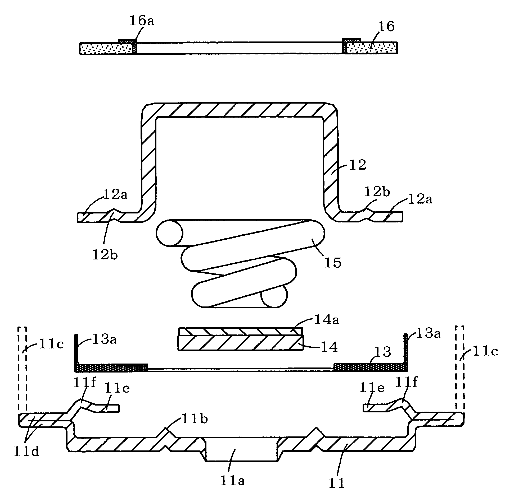
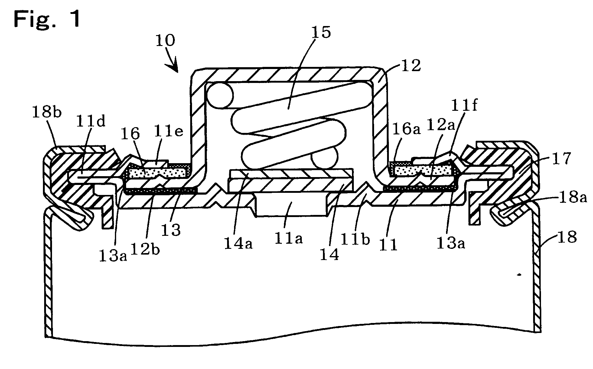
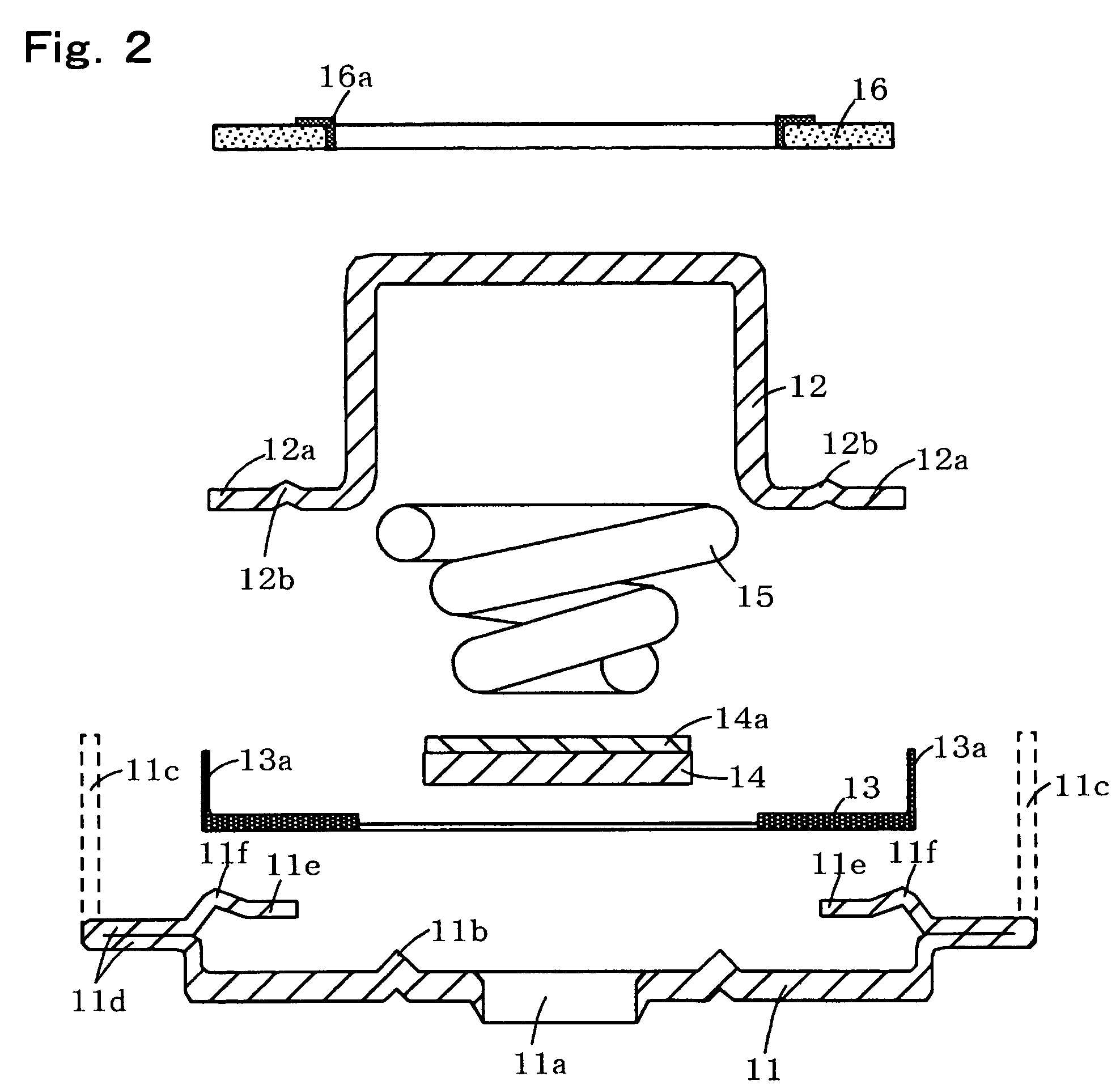
[0027] Preferred embodiments of the present invention will be described hereafter as applied to a nickel-hydrogen battery with reference to FIGS. 1 and 2. Note that the present invention is not restricted to the following embodiments, as proper modification and variation thereof is possible without changing its gist. FIG. 1 is a sectional view typically showing an essential part of a hermetically sealed battery comprising an opening-sealing unit mounted on the opening of an outside can, and FIG. 2 is an exploded view showing components of the opening-sealing unit illustrated in FIG. 1.

[0028] 1. Opening Close Unit

[0029] As shown in FIGS. 1 and 2, the opening-sealing unit 10 according to the present invention comprises a bottom plate 11 for sealing the opening of the outside can 18, a positive electrode cap 12 serving as a positive electrode terminal and forming a space (valve chamber) for housing a pressure valve therein, an insulation ring 13, a resilient valve 14 having a nickel-...


PUM


Abstract

A hermetically sealed battery with an opening-sealing unit 10 according to the present invention comprises a PTC element ring 16 elastically clamped between the flange 12a of a positive electrode cap 12 and a fold portion 11d formed at the peripheral portion 11c of a bottom plate 11, such that when the temperature of the PTC element rises due to overcurrent or overheating, the PTC element ring 16 can easily expand, thereby tripping the large current with its resistance capacity increased to a predetermined level at a predetermined temperature, thereby enhancing operational security of the battery.

Description

BACKGROUND OF THE INVENTION [0001] 1. Field of the Invention [0002] The present invention relates to a hermetically sealed battery such as a nickel-hydrogen battery (nickel-hydrate battery), nickel-cadmium battery, or lithium ion battery and, particularly, to a hermetically sealed battery comprising an opening-sealing unit including a pressure valve residing in a valve chamber composed of a cap portion serving also as a terminal and a bottom plate for closing the opening of an outside can, and a Positive Temperature Coefficient (PTC) element having the property of expanding due to overcurrent or overheating thereby causing a sudden increase in the resistance value at a prescribed temperature or higher, the PTC element being affixed to a part of the opening sealing unit. [0003] 2. Description of the Related Art [0004] Generally, a hermetically sealed battery such as a nickel-hydrogen battery, or a nickel-cadmium battery and the like is operated at an applied voltage of about 1.2V in ...

Claims


Application Information

Patent Timeline
IPC IPC(8): H01M10/34H01M10/52H01M50/171
CPCH01M2/0413H01M2/1229H01M2/345Y02E60/124H01M10/34H01M10/345H01M2200/106H01M2/348Y02E60/10H01M50/171H01M50/325H01M50/578H01M50/581
Inventor KAWANO, KATSUYATADOKORO, MOTOOOBARA, TAKAMASAYOSHINARI, FUMIYOSHI
Owner KAWANO KATSUYA
Why Eureka
Try Eureka