Method of effecting heating and cooling in reduced pressure atmosphere

a technology of atmosphere and heating and cooling, applied in the field of effecting heating and cooling in reduced pressure atmosphere, can solve the problems of not taking the necessary steps to effect both heating and cooling efficiently, the total requisite time for heating and cooling is reduced, and the effect of improving efficiency

Inactive Publication Date: 2005-02-10
CANON KK
View PDF3 Cites 6 Cited by
  • Summary
  • Abstract
  • Description
  • Claims
  • Application Information

AI Technical Summary

Benefits of technology

[0014] In a first aspect of the present invention, in heating the plate-like member by a heat generating member (heating means) and cooling it by the cooling plate, the emissivity of the cooling plate is appropriately selected. In other words, the emissivity is selected such that the cooling plate has both a heat reflecting function and a cooling function, whereby the total requisite time for heating and cooling is reduced.
[0015] More specifically, by setting the emissivity of the cooling plate at a value within a specific range (a value not less than 0.50 but not more than 0.80), an improvement in efficiency is achieved for both the heating processing and the cooling processing. That is, the “cooling plate” used in the heating / cooling processing of the present invention provides, in the cooling process, the basic effect of absorbing heat ray radiated from the heated plate-like member (the object of heating), and, at the same time, provides, in the heating process, the effect of reflecting the heat ray radiated from the heating means toward the object of heating. Thus, the cooling plate is capable of performing the main function of absorbing heat ray radiated from the plate-like member at the time of cooling process, while, at the time of heating process, the cooling plate can re-radiate (by reflection) the heat ray from the heating means toward the plate-like member, so that it is possible to achieve an improvement in heating efficiency. As a result, the total requisite processing time for the heating process and the subsequent cooling process can be reduced.
[0016] In a second aspect of the present invention, when heating / cooling a substrate having on one side a component whose heat capacity is smaller than that of the substrate, or a substrate whose emissivity differs between the front and back sides, the arrangement of the heating means and the cooling plate with respect to the substrate is specified, whereby generation of heat distribution in the substrate is prevented, and uniform and efficient heating / cooling is realized. That is, a substrate having on one side thereof a component (e.g., a spacer) whose emissivity is less than that of the substrate is heated / cooled, with the heating means and the cooling plate being arranged so as to face the other side of the substrate, whereby it is possible to prevent the component with small heat capacity from being more abruptly heated / cooled than the substrate. As a result, cracking of the spacer due to abrupt heating / cooling is prevented, and it is possible to realize uniform and efficient heating / cooling of the substrate and the component (spacer) with small heat capacity. Further, a substrate whose emissivity distribution differs between the surface with wiring and the surface with no wiring as a result of the formation of wiring or the like on one surface, for example, a substrate whose surface with wiring has a larger emissivity than its surface with no wiring, is heated / cooled, with the heat generating member and the cooling member being arranged so as to face the surface with no wiring, whereby it is possible to maintain the heat inflow to the substrate and the heat emission from the substrate uniform. As a result, the temperature distribution generated in the substrate is mitigated, thereby preventing distortion and cracking of the substrate.

Problems solved by technology

If an attempt is made to assemble the face plate and the rear plate under reduced pressure without performing this baking processing, a reduction in pressure is not easily achieved due to degassing attributable to chemical adsorption water, and it takes a rather long time to achieve the target vacuum degree for assembly.
However, in the above prior-art technique, while consideration is given to a well-balanced cooling in a short time through a combination of natural cooling and a cooling gas flow, no measures are taken to effect both heating and cooling efficiently, and there has been a demand for an improvement in this regard.
Further, in the above-described display apparatus, which has structures, such as a rear plate, a face plate, and a spacer, it is necessary to perform baking on each structure; however, performing baking on these structures individually results in an increase in processing time, which is undesirable.
Further, in performing baking in a vacuum, heat distribution may be generated in the rear plate, face plate, spacer, etc., depending on their configuration, which means there is a danger of distortion or cracking being generated in these components.

Method used


Image

  • Method of effecting heating and cooling in reduced pressure atmosphere
  • Method of effecting heating and cooling in reduced pressure atmosphere

Examples


Embodiment Construction

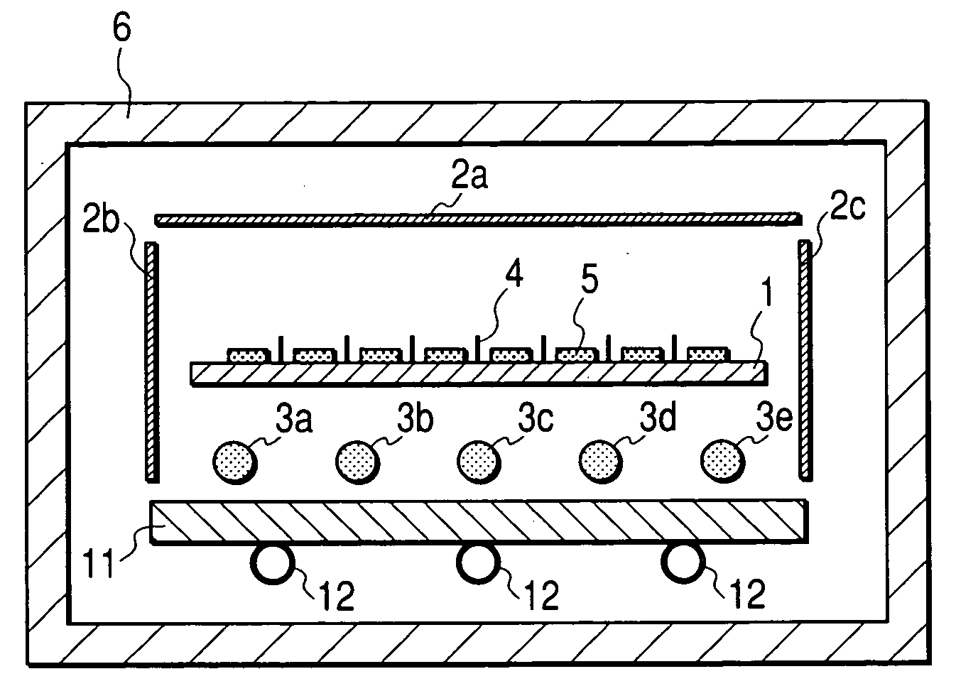
[0019]FIG. 1 is a sectional view of an apparatus used in a heating / cooling method of the present invention, showing the features of the present invention most clearly.

[0020] Reference numeral 1 indicates a substrate, reference numerals 2a through 2c are reflection plates constituting heat reflecting members, reference numerals 3a through 3e indicate heaters serving as heat generating members (heating means), reference numeral 4 indicates spacers, reference numeral 5 indicates on-substrate matter, reference numeral 6 indicates a vacuum chamber, reference numeral 11 indicates a cooling plate constituting a cooling member also having a heat reflecting function, and reference numeral 12 indicates cooling pipes.

[0021] In the drawing, the substrate 1 is an electron source substrate constituting a component of the container of an image display apparatus; on the surface of the substrate 1 (on the upper side as seen in the drawing), there is fixed the on-substrate matter 5, which consists ...


PUM

PropertyMeasurementUnit
emissivityaaaaaaaaaa
surface emissivityaaaaaaaaaa

Abstract

The present invention provides a method of effecting high temperature vacuum heating and cooling suitable for conducting heat treatment to be performed on components used in a display apparatus. The present invention's heating/cooling method comprises the steps of: heating a plate-like member placed in a reduced pressure atmosphere in a chamber by heating means opposed to the plate-like member; and cooling the plate-like member by a cooling plate which is opposed to the plate-like member, with the heating means therebetween, the cooling plate having a heat reflecting function. In one aspect of the present invention, the cooling plate is designed to have a emissivity of not less than 0.50 but not more than 0.80 so as to minimizes a sum of a requisite time for the heating step and a requisite time for the cooling step. In another aspect of the present invention, the plate-like member to be heated has two main surfaces differing from each in an in-plane distribution of emissivity and the heating means is opposed to one of the two main surfaces, which has a smaller distribution ratio, thereby realizing uniform and efficient heating/cooling.

Description

BACKGROUND OF THE INVENTION [0001] 1. Field of the Invention [0002] The present invention relates to a method of effecting high temperature vacuum heating and cooling suitable for conducting heat treatment such as baking to be performed on components used in a display apparatus or the like. [0003] 2. Related Background Art [0004] Conventionally, apart from a liquid crystal display and a plasma display, an image display apparatus is available in which an electron beam is applied to a phosphor to display an image. The image display apparatus using an electron beam has a substrate face plate on which a phosphor is formed, a substrate rear plate on which there is formed, as an electron source for emitting an electron beam, a cold cathode device, such as a surface conduction type electron emission element, and an external frame for maintaining a reduced pressure atmosphere between the two substrates. In such an image display apparatus using an electron beam, an accelerated electron beam ...

Claims


Application Information

Patent Timeline
Patent Type & Authority Applications(United States)
IPC IPC(8): F27B5/14F27B17/00F27D9/00F27D19/00F27D99/00
CPCF27B17/0016F27D99/0001F27D19/00F27D9/00
Inventor KAMATA, SHIGETOKIMURA, AKIHIRO
Owner CANON KK
Why Eureka
Try Eureka