
Positioning apparatus and method for manufacturing same

a technology of positioning apparatus and manufacturing method, which is applied in the direction of photomechanical treatment, instruments, printing, etc., can solve the problems of reduced positioning accuracy, low control system gain characteristics, and vibration of the mounted stage for position measurement, so as to achieve high controllability, not easily deformed by heat, and high accuracy

Inactive Publication Date: 2005-02-17
CANON KK
View PDF9 Cites 11 Cited by
  • Summary
  • Abstract
  • Description
  • Claims
  • Application Information

AI Technical Summary

Benefits of technology

[0019] The present invention provides a positioning apparatus including a movable body having excellent controllability, and which can be positioned at high speed and with high accuracy.
[0031] In order to prevent deformation of the top plate unit, the mirrors, the wafer, etc., due to heat emitted from the actuators, coils of the actuators may be attached to the X stage. A pipe or a wire for feeding electricity, gas, or liquid from the upper plate of the X stage to the wafer chuck, etc., mounted on the top plate unit may be disposed at either a central area or a peripheral area of the top plate unit. In such a case, the vibration transmissibility due to the pipe or the wire is reduced.
[0034] As described above, according to the present invention, the top plate unit, which serves as a movable body in the positioning apparatus, is composed of at least one of a low thermal expansion material having a coefficient of thermal expansion of 1.0e−6 (1 / ° C.) or less, an inorganic fiber composite, and a SiC composite containing SiC and Si, in an integral, hollow structure. Accordingly, a light, strong, rigid top plate unit that is not easily deformed by heat is obtained. In addition, due to the electromagnetic couplings and the Lorentz force actuators of the top plate unit, a positioning apparatus having a high controllability is obtained. Furthermore, when a lapping process is performed after the particles are injected into the hollow section, a constant surface pressure is applied, so that the surface can be processed with high accuracy.

Problems solved by technology

When vibration of the stage components occurs, the mirrors mounted on the stage for position measurement also vibrate and the positioning accuracy is reduced.
In addition, since oscillation occurs at the natural frequency when the gain is too high, the gain characteristics of the control system are limited.
However, when a material having a small coefficient of thermal expansion is used in order to suppress the thermal deformation of the top plate unit 411, there is the risk that sufficient bonding strength cannot be obtained.
In addition, when an adhesive is used for bonding the members together, there is the risk that sufficient adhesive strength and adhesive reliability cannot be obtained.
However, in such a case, it is extremely difficult for the Lorentz force actuators (linear motors) to generate enough force to hold the weight of the top plate, the wafer and the wafer chuck mounted on the top plate as well as to accelerate them because of restrictions on the size of the motors and heat emitted from the motors.
Accordingly, materials having small coefficients of thermal expansion cannot be used.
In addition, when an adhesive is used, differences occur between components even when they are formed in the same shape, and the natural frequency of the combined unit cannot be as high as a calculated or theoretical value because of differences between adhesion conditions.
This degrades the environment around the wafer, and a problem occurs in that the alignment accuracy and stage accuracy are adversely affected and productivity is reduced when high-speed micromachining of semiconductor devices is required.

Method used


Image

  • Positioning apparatus and method for manufacturing same
  • Positioning apparatus and method for manufacturing same
  • Positioning apparatus and method for manufacturing same

Examples


first embodiment

[0055] First Embodiment

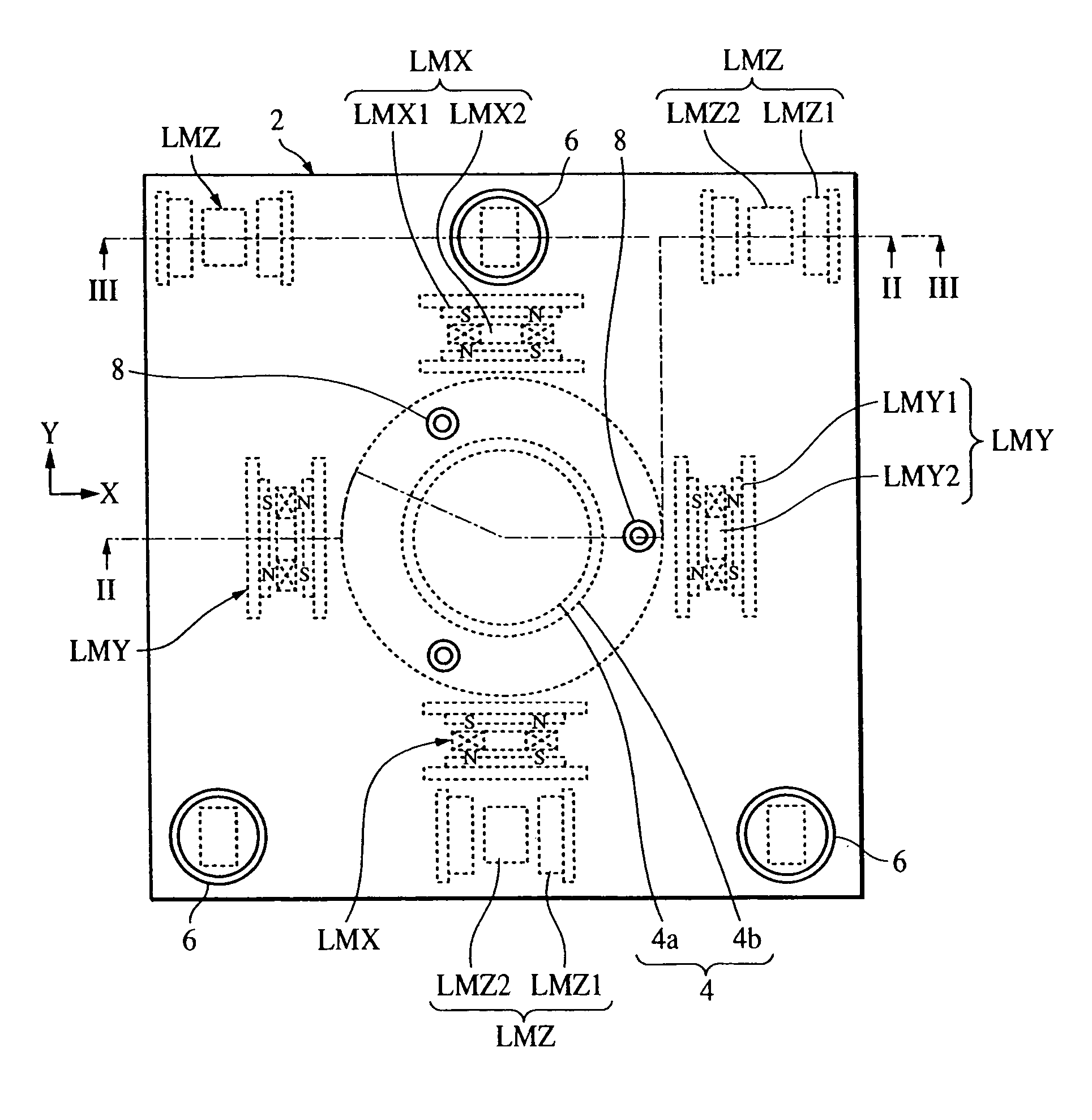
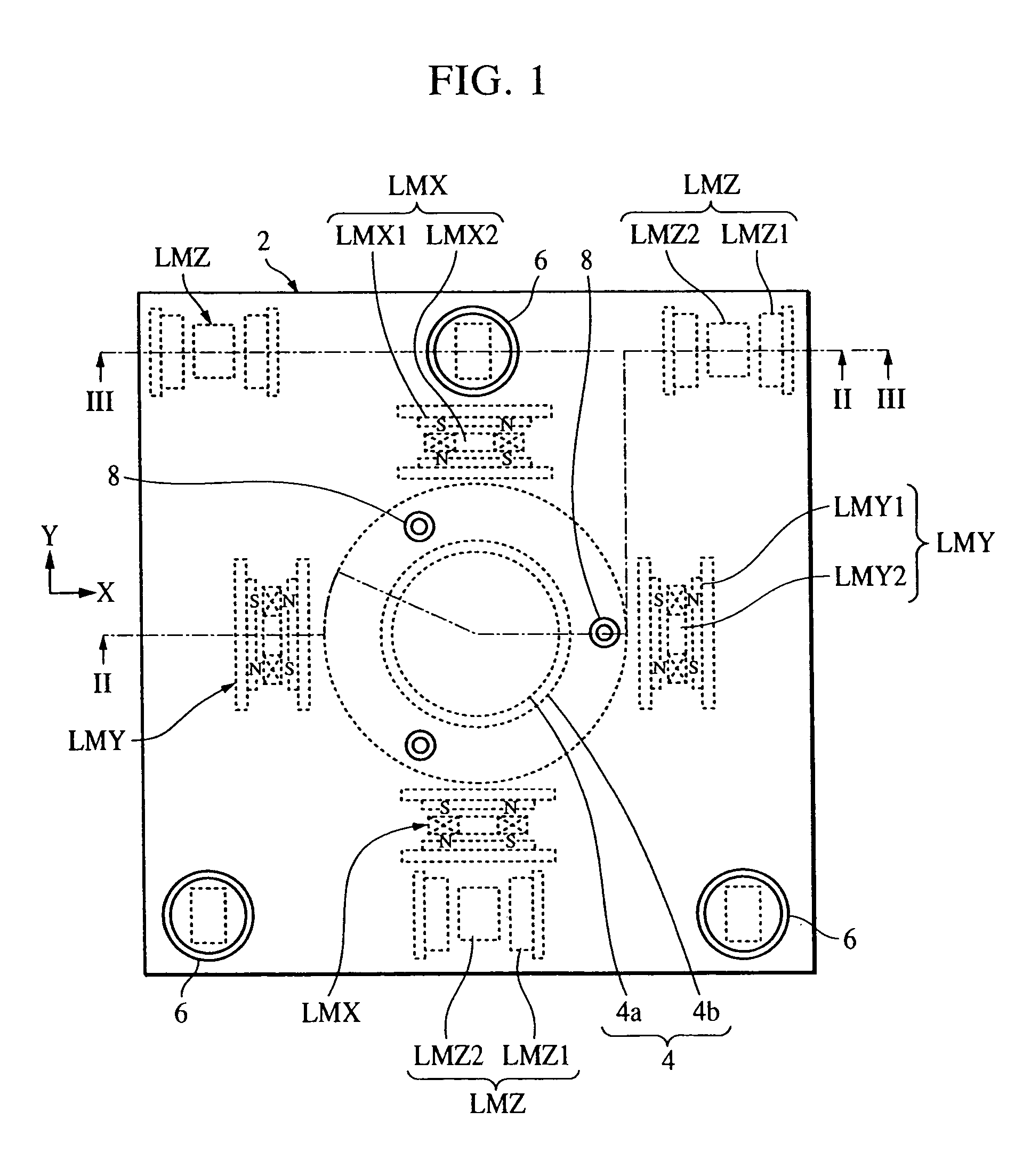
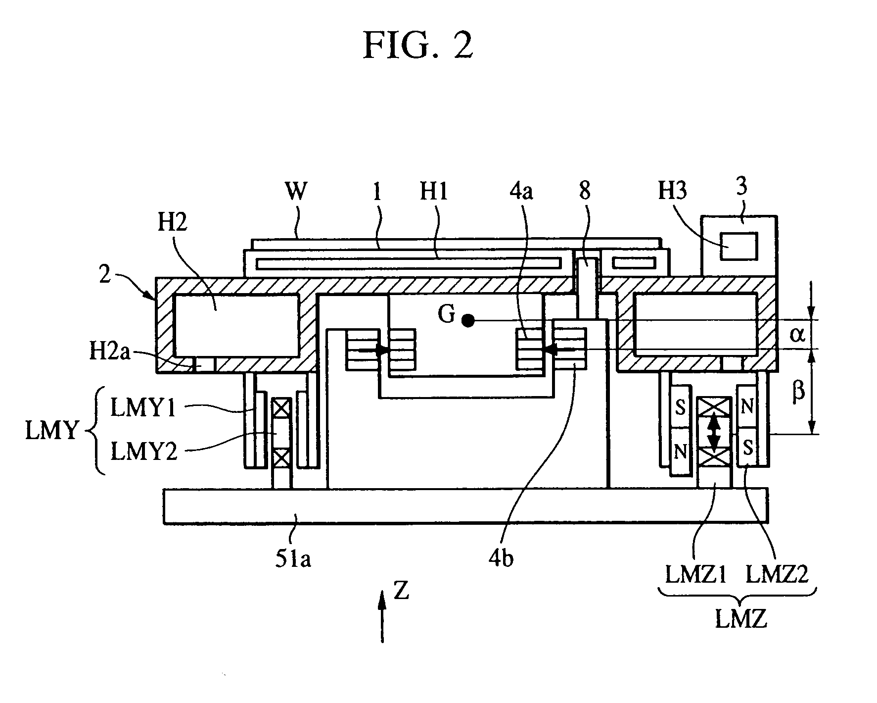
[0056]FIG. 1 is a schematic top view of a top plate included in a positioning apparatus according to a first embodiment of the present invention and peripheral regions thereof. FIG. 2 is a sectional view of FIG. 1 cut along line II-II and FIG. 3 is a sectional view of FIG. 1 cut along line III-III. The positioning apparatus includes a wafer chuck 1 which serves as a first plate unit, a hollow plate unit 2 which serves as a second plate unit and retains the chuck 1, a mirror 3, electromagnetic couplings 4, weight-compensation mechanisms 6, supporting rods 8, and X-direction fine-movement linear motors LMX, Y-direction fine-movement linear motors LMY, and Z-direction fine-movement linear motors LMZ used for finely adjusting the position of the hollow plate unit 2, etc. The above-described components are disposed on an upper plate 51a of an X stage.

[0057] The hollow plate unit 2 shown in the figures is constructed by first forming an integral, hollow structure, ...

second embodiment

[0089] Second Embodiment

[0090]FIG. 7 is a schematic sectional view of a positioning apparatus according to a second embodiment of the present invention which includes a mirror-combined hollow plate unit constructed by adhering or mechanically fixing an optical mirror 3 on a hollow plate unit 2 at a side surface thereof.

[0091] In order to avoid deformation of the hollow plate unit 2 due to the difference in coefficient of thermal expansion, the optical mirror 3 and the hollow plate unit 2 are formed of the same material. Since they are integrally formed using the same material, the displacement of the mirror 3 due to the acceleration of the stage movement can be prevented. In addition, since the mirror 3 is retained by the hollow plate unit 2 having a high rigidity, deformation of the mirror 3 can also be prevented.

[0092] Pipes, wires, etc., used for transferring electricity, gas, and liquid to the chuck 1 and sensors (not shown) mounted on the hollow plate unit 2 from the upper pl...

third embodiment

[0096] Third Embodiment

[0097]FIG. 8 is a diagram showing a positioning apparatus according to a third embodiment of the present invention. In FIG. 2, the hollow plate unit 2 includes a solid-plate area at a region where the movable members 4a of the electromagnetic couplings 4 are attached. However, in such a case, the hollow plate unit 2 will be deformed if the acceleration applied to the electromagnetic couplings 4 is large. When the hollow plate unit 2 is deformed, the chuck 1 is also deformed, and as a result, the wafer W is also deformed so that an alignment error occurs. Therefore, according to the third embodiment of the present invention, in order to increase the strength of the hollow plate unit 2, the region of the hollow plate unit 2 where the movable members 4a of the electromagnetic couplings 4 are attached is also formed in a hollow structure instead of merely increasing the thickness thereof, so that the weight is reduced and the rigidity is increased.


PUM


Abstract

A positioning apparatus includes a wafer chuck which retains a wafer and a hollow plate unit which retains the chuck, which is composed of a ceramic material in an integral, hollow structure having a hollow section, the hollow section having a rib structure which serves to increase the natural frequency of the hollow plate unit with respect to torsional mode vibration, and which has holes for providing connection between the interior and exterior of the hollow section. The rib structure is constructed such that a rib unit having a rectangular shape in cross section, the sides thereof extending along X and Y fine movement directions, and a rig unit having a diamond shape in cross section are alternately disposed inside each other and are bonded to each other.

Description

BACKGROUND OF THE INVENTION [0001] 1. Field of the Invention [0002] The present invention relates to a positioning apparatus for a stage or the like used in an apparatus or method for manufacturing devices such as semiconductor devices and liquid crystal displays. The positioning apparatus is used in, for example, a projection exposure apparatus, various precise processing apparatuses and measuring apparatuses, etc., for moving and positioning a substrate such as a semiconductor wafer, a mask, and a reticle at high speed and with high accuracy. In addition, the present invention may also be applied to a method for manufacturing a semiconductor device by using an exposure apparatus incorporating such a positioning device. [0003] 2. Description of the Related Art [0004]FIG. 12 shows a perspective view of an XY stage as an example of a known positioning device. A positioning device of this type is disclosed in, for example, Japanese Unexamined Patent Application Publication No. 8-22975...

Claims


Application Information

Patent Timeline
IPC IPC(8): H01L21/027G12B5/00H01L21/68
CPCG03F7/70716H01L21/68G03F7/709
Inventor KUBO, HIROYOSHI
Owner CANON KK
Learn More