Wavelength selective optical switch

a selective optical switch and wavelength technology, applied in the direction of multiplex communication, polarising elements, instruments, etc., can solve the problems of complex construction, complicated construction, complicated alignment, etc., and achieve the effect of simple construction

Inactive Publication Date: 2005-02-17
II VI DELAWARE INC
View PDF8 Cites 70 Cited by
  • Summary
  • Abstract
  • Description
  • Claims
  • Application Information

AI Technical Summary

Benefits of technology

[0006] The present invention seeks to provide a new wavelength selective optical switching device, which is simple in constru

Problems solved by technology

However, most of those devices have one or more disadvantages in that they are either complicated to build, or to align, or utilize expensive

Method used


Image

  • Wavelength selective optical switch
  • Wavelength selective optical switch
  • Wavelength selective optical switch

Examples


Embodiment Construction

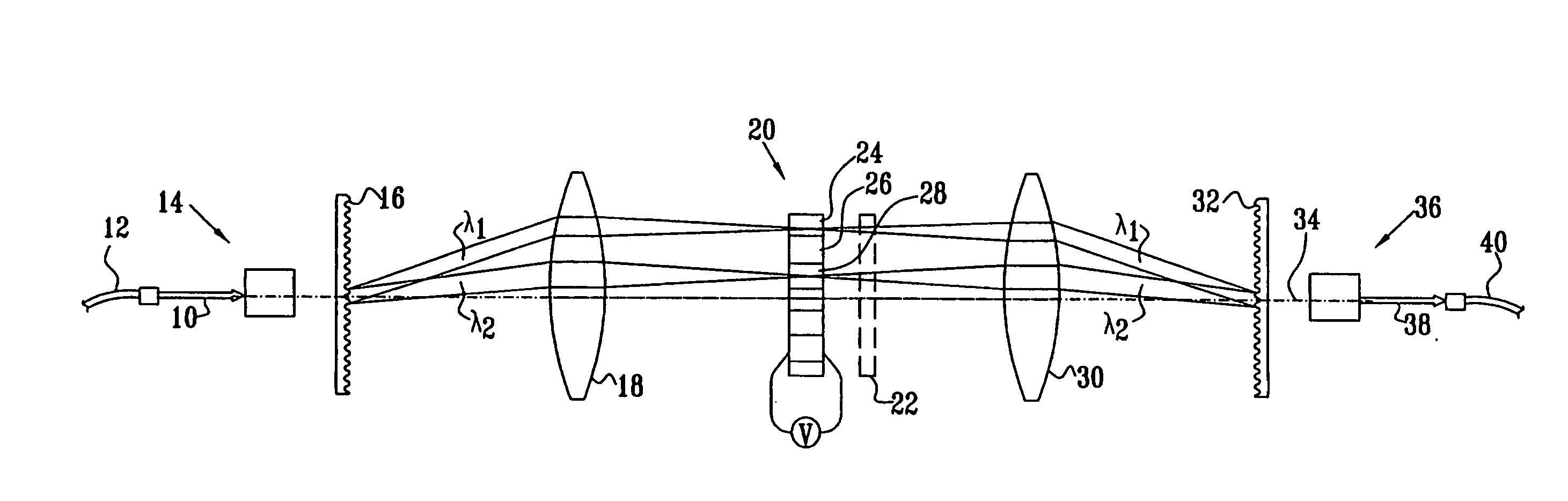
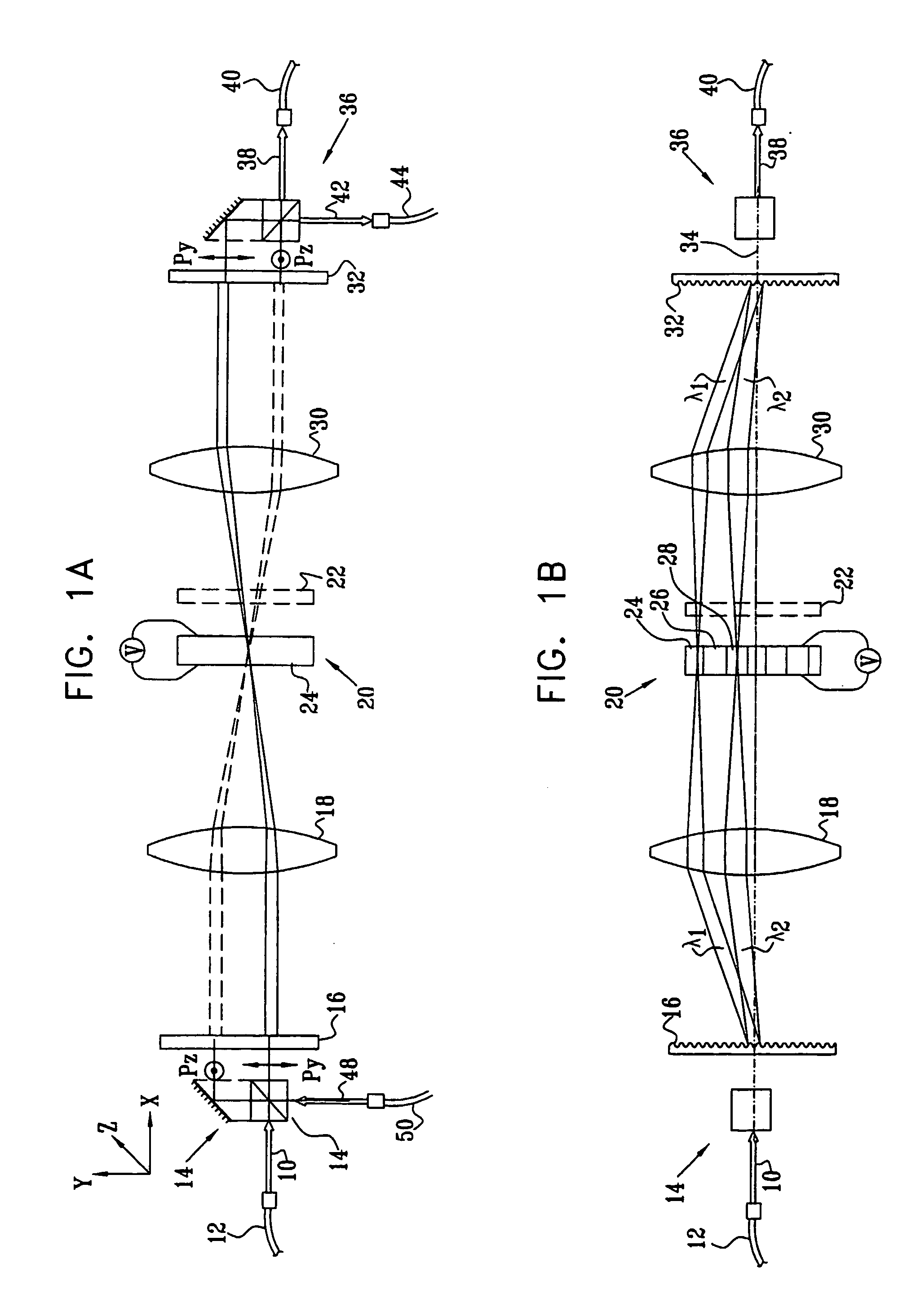
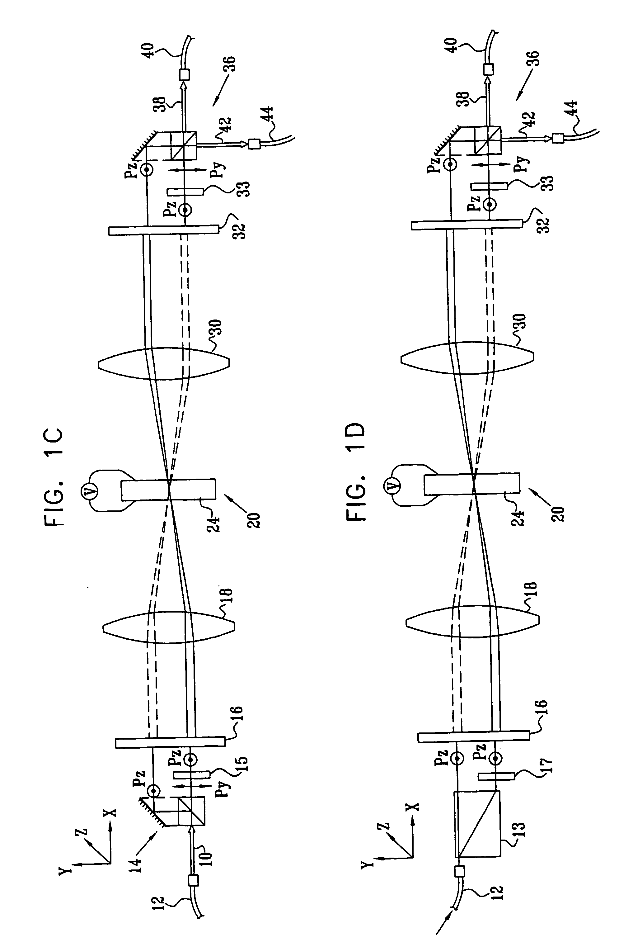
[0035] Reference is now made to FIGS. 1A and 1B, which illustrate schematically different views of a wavelength selective optical switch, constructed and operative according to a first preferred embodiment of the present invention. FIG. 1A is a view of the device from one plane, known as the polarization splitting plane, while FIG. 1B is a view of the same device as seen from a plane preferably orthogonal to the first and known as the wavelength dispersion plane. The operation of the wavelength selective optical switch can be understood by reference simultaneously to the signal paths shown in FIGS. 1A and 1B.

[0036] An input optical signal 10, such as would be obtained after collimation from the end of an optical fiber 12, is input into a polarization beam splitter (PBS) 14, shown in FIG. 1A as a split prism PBS, though it is to be understood that other preferred types of PBS may also be used for this function. The PBS is so orientated that it preferably splits the input signal into...


PUM


Abstract

A wavelength selective switch, in which an input optical signal is wavelength-dispersed and polarization-split in two angularly oriented planes. A polarization rotation device, such as a liquid crystal polarization modulator, pixelated along the wave-length dispersive direction such that each pixel operates on a separate wavelength channel, rotates the polarization of the light signal passing through the pixel, according to the control voltage applied to that pixel. The polarization modulated signals are then wave-length -recombined and polarization-recombined by means of similar dispersion and polarization combining components as were used to respectively disperse and split the input signals. The direction of the output signal is determined by whether the polarization of a particular wavelength channel was rotated by the polarization modulator pixel, or not. In this way, a fast, wavelength dependent, optical switch is provided, capable of use in WDM switching applications.

Description

FIELD OF THE INVENTION [0001] The present invention relates to the field of devices for the switching of optical signals, according to the wavelength of the light bearing the information, by means of spatially selective polarization rotation of the light, especially for use in optical communication networks. BACKGROUND OF THE INVENTION [0002] Fast all-optical switching of information is an essential element of modem optical communication systems, enabling the slower electronic functions to be reserved only for the input and output terminals of the network, where the speeds required are those of individual channels, and not of the network throughput. In WDM systems, the information is segregated with regard to its source and destination according to the wavelength of the particular optical signal being transferred, and a switch for use in such a system must therefore be able to route each signal automatically according to its wavelength. [0003] There exist a number of prior art devic...

Claims


Application Information

Patent Timeline
IPC IPC(8): G02F1/061G02B6/34G02B6/35G02B27/28G02F1/13G02F1/1333G02F1/31H04Q11/00
CPCG02B6/272G02B6/2766G02B6/2931G02B6/29311G02B6/29313G02B6/2938H04Q2011/0035G02F1/1326G02F1/31G02F2203/05H04Q11/0005H04Q2011/0024G02B6/29395
Inventor COHEN, GILSILBERBERG, YARONCOREM, YOSSI
Owner II VI DELAWARE INC
Why Eureka
Try Eureka