High power pulse shaping fiber laser for high data rate free space telecommunication systems

a fiber laser and data rate technology, applied in electromagnetic transmission, transmission, active medium materials, etc., can solve the problems of reducing transmission distance, limiting conventional technologies for providing high-power fiber laser sources for future free space telecommunication systems, and potential optical damage of internal components of laser sources

Active Publication Date: 2005-02-17
LIU JIAN
View PDF15 Cites 38 Cited by
  • Summary
  • Abstract
  • Description
  • Claims
  • Application Information

AI Technical Summary

Benefits of technology

It is therefore an object of the present invention to provide a laser source that includes components to carry out

Problems solved by technology

Conventional technologies for providing high power fiber laser sources for future free space telecommunication systems are still limited by several technical difficulties.
The high power leading edge causes potential optical damages of the internal components of the laser source and further reduces the transmission distance due to a non-transform limited pulse shape.
The sharp leading edge of the laser pulses when projected into the optical components in an optical transmission system generates a high-energy shock over very short time duration.
This instantaneous energy shock may well be over the damage threshold of the components, e.g., the damage thresholds of the photo-detectors and optical filters, and thus cause instantaneous system malfunction and that often leads to permanent damage.
Moreover, for an optical communication system, the higher power density caused by these sharpened temporal responses and higher leading edge of the laser pulse are often detrimental to the detection subsystem due to the energy transfer to the Stokes lines now provided with a stronger fiber amplifier.
Another technical difficulty that often limits the capabilities of a fiber laser source is related to the laser chirp due to modulation and self phase modulation (SPM) that leads to distortions of the laser pulses.
As a result, when the signals are transmitted over a distance over a dispersive medium, more distortions are increasingly intro

Method used


Image

  • High power pulse shaping fiber laser for high data rate free space telecommunication systems
  • High power pulse shaping fiber laser for high data rate free space telecommunication systems
  • High power pulse shaping fiber laser for high data rate free space telecommunication systems

Examples


Embodiment Construction

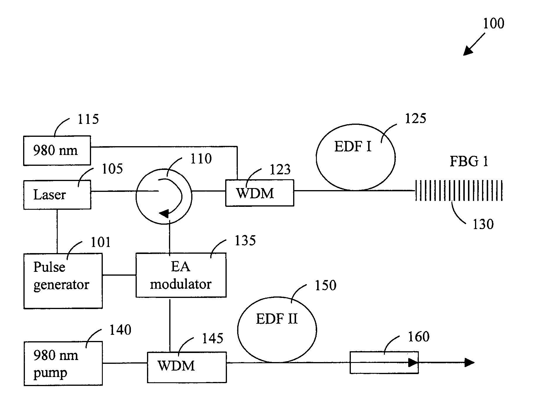
FIG. 2 shows a schematic diagram of an improved laser source of the present invention to resolve the issues of pulse distortion and nonlinear effects such as stimulated Brillouin scattering (SBS), SPM, and stimulated Raman scattering (SRS) by employing a fiber grating with large mode area fiber amplifier, and modulating the source below threshold current to increase the extinction ratio. The high power fiber laser 100 includes a modulated laser diode 105 that sends out a sequence of pulses generated from a pulse generator 101 to pass through a circulator 110 to enter into a first amplification stage powered by a lower power pump laser diode 115 through a first wavelength division multiplexer (WDM) 123 and a high NA EDF-I 125 to amplify the input signal into a low noise amplified signal projected to a fiber Bragg gratings 130. The laser diode 105 is modulated in a way that the pulse generator 101 applies alternative high and low voltages at certain frequency. The laser diode 105 has ...


PUM


Abstract

An amplified laser source for amplifying a laser projection that includes a diode laser source modulated by a pulse generator applying an alternate high and low voltages higher and lower than a threshold voltage for projecting a modulated optical signal. The laser source further includes a first erbium-doped fiber (EDF) for amplifying the modulated optical signal. The laser source further includes a set of Bragg gratings for receiving the modulated optical signal from the first EDF for reflecting a grating-specific pulse-distortion-reduced optical signal. The laser source further includes an electro-absorption (EA) modulator synchronized with the pulse generator for increasing an extinction ratio of the optical signals. The laser source further includes a second erbium doped fiber (EDF) for receiving and amplifying the optical signal from the EA modulator wherein the second erbium doped fiber (EDF) having a length of several meters and a diameter greater than or equal to thirty-five micrometers.

Description

FIELD OF THE INVENTION The present invention relates generally to apparatuses and methods for providing high power laser sources. More particularly, this invention relates to new configurations and methods for providing compact and high power pulse shaping fiber laser suitable for implementation in high data rate free space telecommunication systems. BACKGROUND OF THE INVENTION Conventional technologies for providing high power fiber laser sources for future free space telecommunication systems are still limited by several technical difficulties. Specifically, in the processes of producing high-energy pulses, current techniques and systems tend to sharpen the temporal responses and create a high peak region in the leading edge of the pulse. The high power leading edge causes potential optical damages of the internal components of the laser source and further reduces the transmission distance due to a non-transform limited pulse shape. The sharp leading edge of the laser pulses whe...

Claims


Application Information

Patent Timeline
IPC IPC(8): G02B6/34H01S3/00H01S3/067H01S3/091H01S3/0941H01S3/10H01S3/16H01S3/30
CPCH01S3/005H01S3/0078H01S3/0085H01S3/1608H01S3/0675H01S3/06758H01S3/0941H01S3/06708
Inventor LIU, JIAN
Owner LIU JIAN
Why Eureka
Try Eureka