
Candle having a planar wick and method of and equipment for making same

Active Publication Date: 2005-02-17
LUMETIQUE
View PDF50 Cites 78 Cited by
  • Summary
  • Abstract
  • Description
  • Claims
  • Application Information

AI Technical Summary

Benefits of technology

[0023] Directed to overcoming the foregoing and other shortcomings and drawbacks of candle wicks and systems heretofore known, the present invention embodies a planar wick and the method and equipment to produce the same. In preferred forms, the present invention includes wood, wood-like or semi-wood wicks that provide improved capillary flow as well as increase the functional surface area. This candle wick provides additional decoration and an acoustic release. In accordance with principles of the present invention, a candle wick is provided which is particularly designed to burn efficiently in a candle system without producing undesirable smoke and carbon heading. In addition, the wicks are capable of creating a more stable and uniform wax pool diameter. The candle wick is designed to change the physical shape of the flame to thereby provide maximum burning efficiency. Candles of the present invention provide a safer, cleaner burning, decorative, multi-sensory alternative to the prior wick technology.
[0024] The present invention provides a candle having a body of a meltable fuel and a planar wick. The meltable fuel can be vegetable-based, paraffin, beeswax, carnauba, candelillia, polymers, polyolesters or other “fuels” as would be apparent to those skilled in the art from this disclosure. When the wick is lit, the candle provides a unique flame formation, usable in a variety of decorative applications. The wick can be configured to evenly deplete the meltable fuel, while allowing for candles having relatively large and unique body configurations. Optionally, the body of candle and / or the wick may include scented oil to promote the release of fragrance upon heating and the wick may comprise wood, thereby providing an acoustic contribution to ambiance, improved combustion that generates less soot than conventional candles.

Problems solved by technology

Although there have been improvements in candle systems and wicks over the past century, there are still complications, limitations and hazards associated with prior wick technologies.
They also reported that there had been an increase in the number of candle recalls due to fire safety issues, including excessive flames in gel, terra cotta and metal container candles and various other types of wax candles.
Consequently, the vast options of wicks may be a disadvantage to manufacturers or consumers, adding additional costs and time spent sourcing a proper wick.
Ultimately, braided wicks still have many limitations.
Limitations include the wick's aesthetic appearance, and limited design and ambiance alternatives.
Another limitation with braided wicks is that they do not provide enough capillary flow to optimize the performance of today's candles.
When manufacturing a braided wick, increasing the picks per inch will increase the density of the wick (i.e. reduce the yield) and thereby reduce the size of capillaries, thus reducing the potential flame height or burn rate.
However, such an increase in yield and burn rate from conventional braided candle wicks is limited by the fact that creating a more open structure with large capillaries creates a less stable wick which changes in characteristics when subjected to the tensions of the candle manufacturing process.
In addition, the smooth surface of a braid reduces the functional surface area.
The small capillaries and smooth functional surface area of the braided wick make it more difficult to create the required capillary flow rate in today's natural and gel waxes as well as candles that have high amounts of additives to modify a candle's hardness, color, burn rate and aroma (i.e. stearic acid, UV inhibitors, polyethylene, scent oils and color pigments).
Due to wick height standardization by ASTM (i.e. three inches), braided wicks are limited in size and density, thus resulting in limitations in wax pool size, burn rate and consumption.
Even if a “core” or stiffing agent were applied, the wick still remains too flexible.
The wider and thicker the braided wick is the more unstable and hazardous it may be.
Since the size of the wax pool is related to the burn rate and flame height, braided wicks typically cannot produce a large enough wax pool to consume the majority of a larger candle without compromising the standardized flame height.
This results in additional manufacturing costs, irregular wax pools and potential hazards.
For instance, when one wax pool spills into another, the leaking wax may create unstable flame heights and wick drowning.
Consequently, the wire core technology is manufactured with braided cotton or cotton-like material, generating the same analogous performance complications as disclosed.
This undesirable result can cause a self-trimming braided wick to increase in length so as to increase the amount of wick material, or functional surface area, above the melted wax pool, thereby producing a continually increasing (i.e. unstable) flame height and wax pool.
The flat wicks are unsupported and very flexible.
Due to the flexibility in supported or unsupported woven wicks, several hazards can occur.
Filled candles with flexible wicks, particularly those enclosed in plastic or glass containers, may overheat or contact the side of the container, causing breakage or other damage.
Additionally, unsupported wicks may extinguish themselves, falling into the pool of molten wax.
Further, freestanding candles with an unsupported wick may incur wax spillage due to a decentralized or irregular shaped wax pool.
In April 2003, the Consumer Product Safety Commission (CPSC) banned the manufacture and sale of lead-cored wicks and candles with lead-cored wick because they could present a lead poisoning hazard to young children.
Unfortunately, it is very difficult for consumers to tell if the braided “cored wicks” contain lead.
An additional obstacle with prior art wicks involves keeping a braided candle wick trimmed to a ¼ inch length for proper burning, as recommended by ASTM, NCA and most candle manufacturers and testing labs.
If a braided wick is not trimmed properly, carbon balls, excessive soot emissions and fire hazards may occur.
If a wick is positioned deep in a narrow candle jar or container, it may become difficult for conventional scissors or cutting device to trim off the excess long wick from the candle.
Still, another problem is the difficulty to accurately measure a wick to the exact recommended {fraction (1 / 4)} inch length.
The primary obstruction of prior candle wicks is the emanation of excessive soot developments, resulting in smoke emission and carbon build up.
In addition to creating a polluted looking candle, the liquid fuel may combust, thereby igniting the carbon heads, which become hot enough to vaporize and re-ignite resulting in “flashover.” In freestanding candles, the carbon heads may heat up the wax and burn through the sides and bottom of the candle causing severe damage and fire hazards.
In addition, the development of carbon heads (i.e. “afterglow”) causes the emission of unwanted smoke or toxic fumes to linger for several minutes after being extinguished.
Many wick sustainers are difficult though to position centrally.
Additionally, many wick sustainers are made of materials that are not heat resistant or have “self-extinguish” qualities resulting in the overheating of glass causing severe damage, such as by fracturing or cracking.
Maintaining the wicks centrally in the mold during such operation is a rather difficult procedure, due to the flexibility of braided wicks.
For example, as molten wax cools, it shrinks, causing wick repositioning, which increases the risk of wax spillage as the candle burns.

Method used


Image

  • Candle having a planar wick and method of and equipment for making same
  • Candle having a planar wick and method of and equipment for making same
  • Candle having a planar wick and method of and equipment for making same

Examples


Embodiment Construction

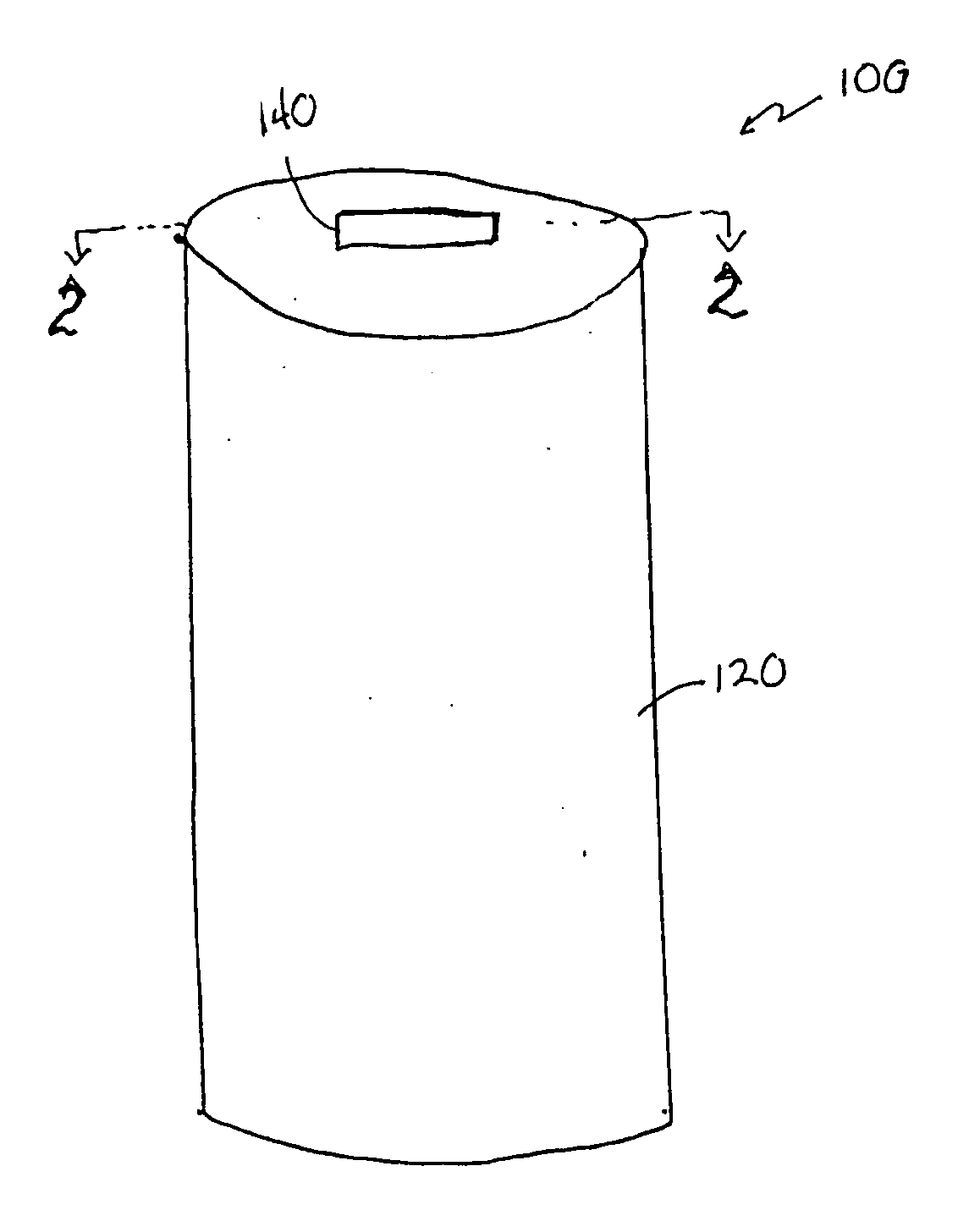
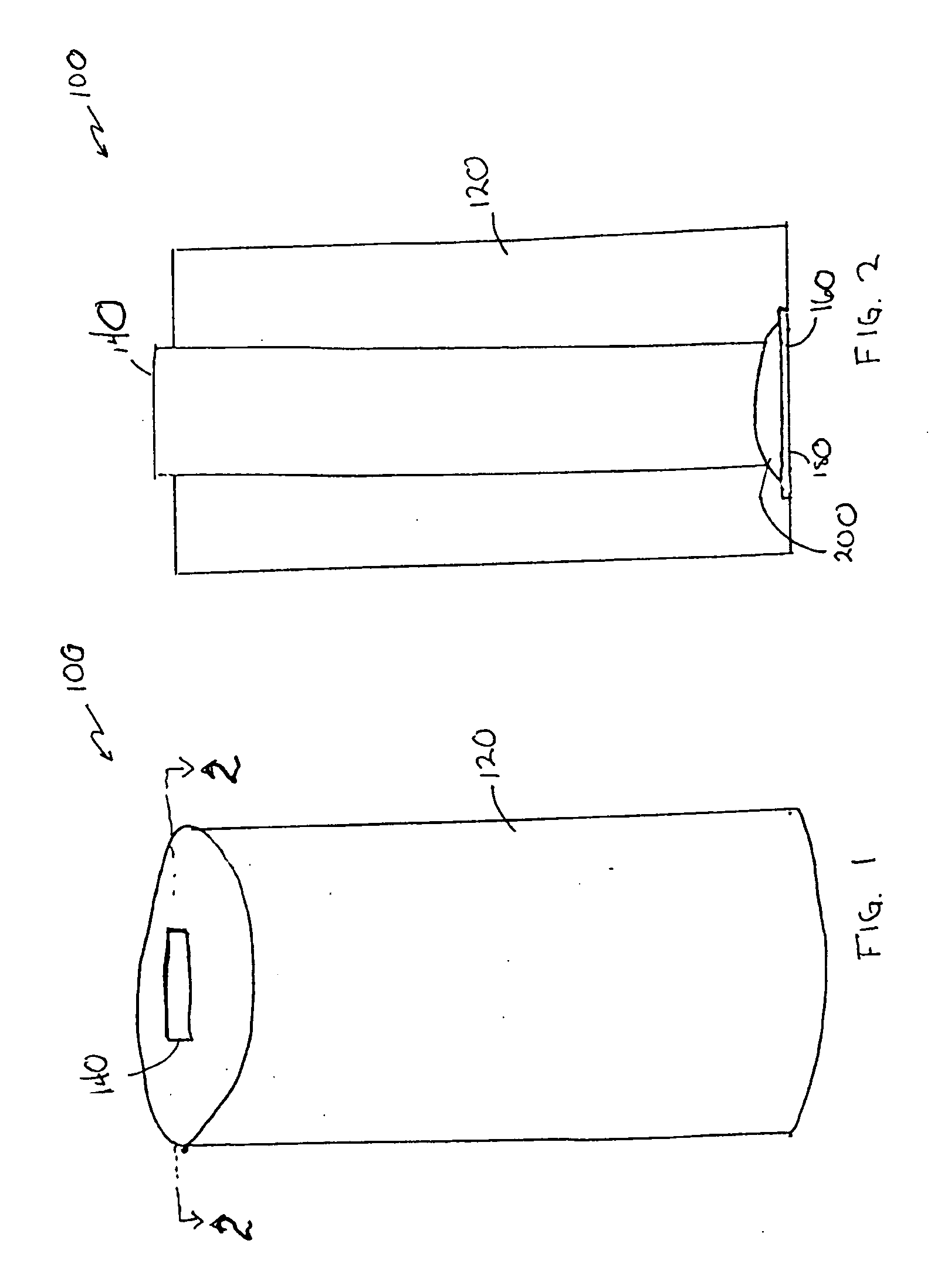
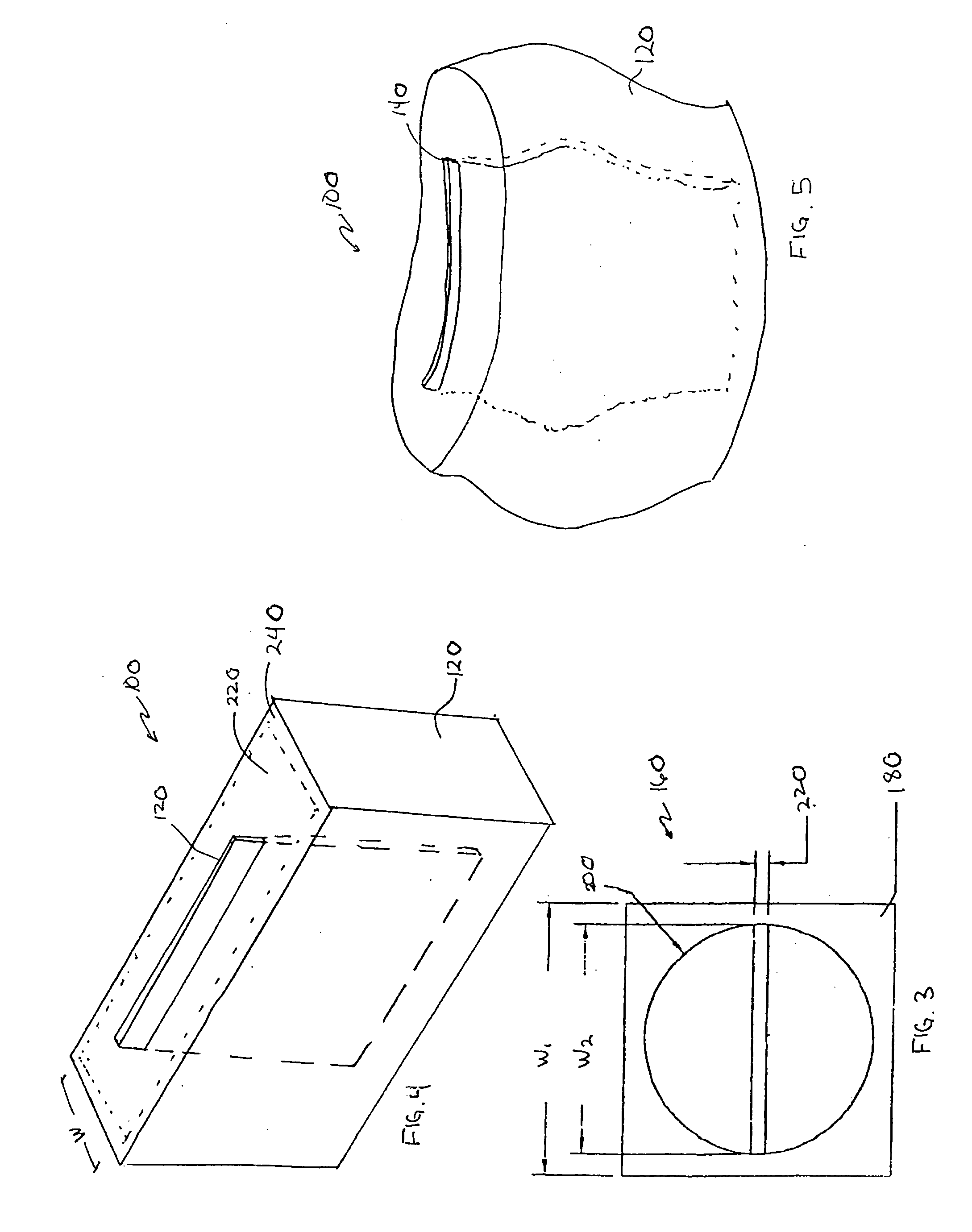
[0068] With reference to the illustrative drawings, and particularly to FIG. 1, there is shown a candle shown generally at 100 having a body 120 of a meltable fuel and a planar wick 140. When lit, the candle 100 provides a unique flame formation usable in a variety of decorative applications. Optionally, the candle body 120 and / or the wick 140 may include scented oil to promote the release of fragrance upon heating, may be bleached, dyed or printed on for decor, and can be configured to provide an acoustic contribution to ambiance.

[0069] The material and thickness of the wick 140 are selected to promote the candle's functionality as well as the candle's contributions to ambiance. In a presently preferred embodiment, the wick 140 is made of wood, semi-wood or wood-like material and, when lit, provides a pleasant crackling sound and burns more thoroughly with less carbon heading and sooting than conventional wicks. Processed wood materials such as particleboard and fiberboard may als...


PUM


Abstract

A candle having a body of a meltable fuel and a planar wick. When lit, the candle provides a unique flame formation, usable in a variety of decorative applications. The wick can be configured to evenly deplete the meltable fuel, while allowing for candles having relatively large and unique body configurations. The body of candle and / or the wick may include scented oil to promote the release of fragrance upon heating. The wick preferably is formed of wood, thereby providing an acoustic contribution to ambiance and improved combustion that generates less soot than conventional cotton wick candles.

Description

CROSS REFERENCE TO RELATED APPLICATIONS [0001] This is a continuation-in-part of copending application Ser. No. 10 / 300,695, filed Nov. 19, 2002, which claims the benefit of U.S. Provisional Application No. 60 / 331,898, filed Nov. 19, 2001. The entire contents of the '695 application are hereby incorporated by reference.BACKGROUND OF THE INVENTION [0002] Historically, candles served a functional purpose, but today they are further used to enhance decoration, aroma and ambiance. References to candles date back to at least 3000 B.C. in Crete and Egypt. Candle making as known today, began in the 13th Century. Candle molding machines were developed in the 15th Century. The braided wick was introduced in 1825. A continuous wicking machine was invented in 1834. Manufactured paraffin was introduced in 1850, providing an alternative to tallow. In 1854 paraffin and stearin were combined to create stronger candles, very similar to those used today. Through the past century, a number of “modern”...

Claims


Application Information

Patent Timeline
IPC IPC(8): F23D14/16F23D14/18
CPCF23D3/16F23D3/08
Inventor DECKER, DAYNA M.
Owner LUMETIQUE
Learn More