

Membrane Distillation Apparatus and Methods
- Summary
- Abstract
- Description
- Claims
- Application Information
AI Technical Summary
Benefits of technology
Problems solved by technology
Method used
Image

Examples
Embodiment Construction
[0038]The following is a detailed description of the invention provided to aid those skilled in the art in practicing the present invention. Those of ordinary skill in the art may make modifications and variations in the embodiments described herein without departing from the spirit or scope of the present invention. Unless otherwise defined, all technical and scientific terms used herein have the same meaning as commonly understood by one of ordinary skill in the art to which this invention belongs. The terminology used in the description of the invention herein is for describing particular embodiments only and is not intended to be limiting of the invention. All publications, patent applications, patents, figures and other references mentioned herein are expressly incorporated by reference in their entirety.
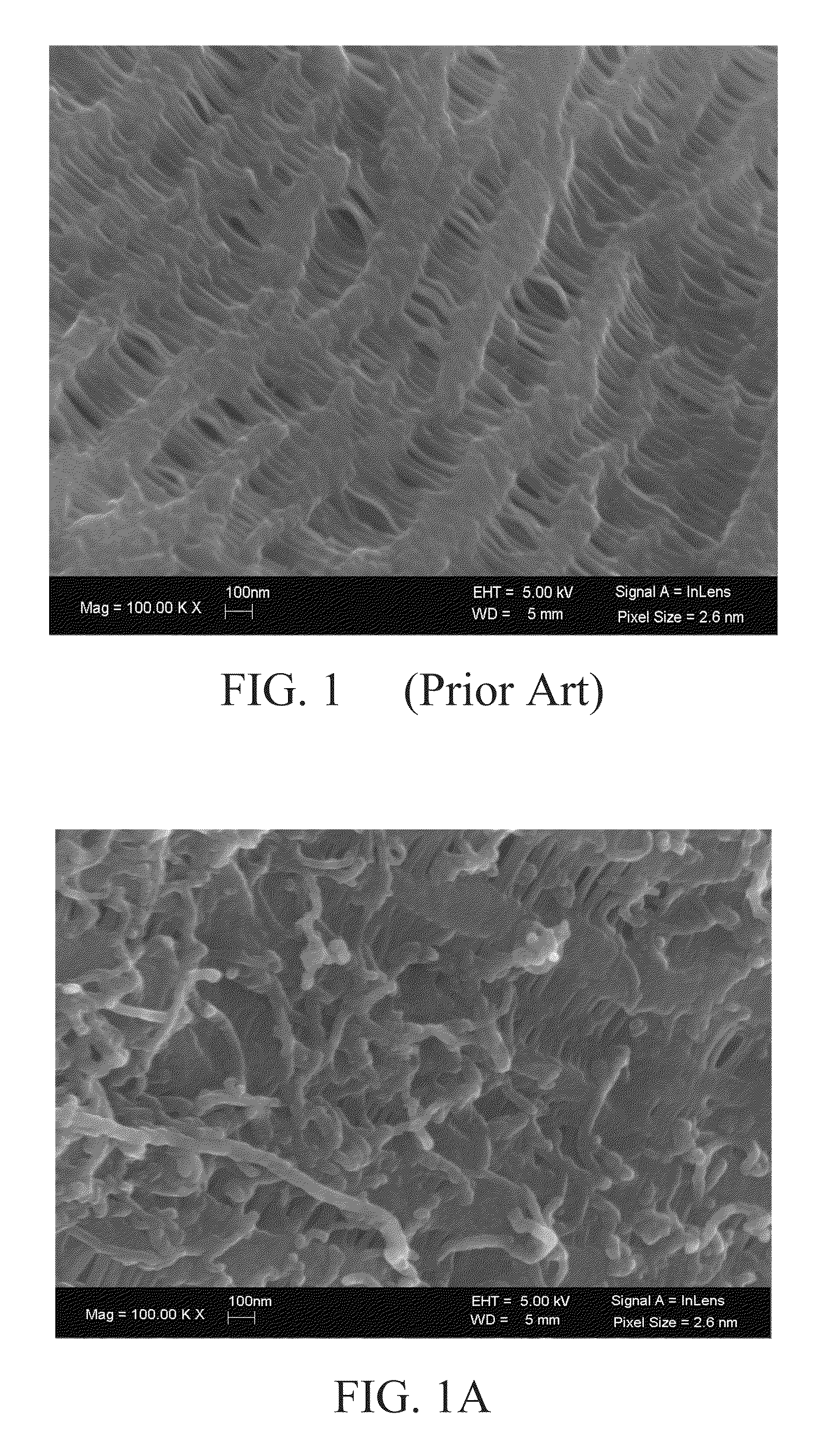
[0039]Now referring to FIG. 1, a prior art membrane for membrane distillation is shown. Now referring to FIG. 1A, a membrane for membrane distillation in accordance with the pr...
PUM
| Property | Measurement | Unit |
|---|---|---|
| Fraction | aaaaa | aaaaa |
| Fraction | aaaaa | aaaaa |
| Fraction | aaaaa | aaaaa |
Abstract
Description
Claims
Application Information