
Grain alcohol distillation plants

a technology of grain alcohol and distillation plants, which is applied in the direction of distillation separation, biofuels, vapor condensation, etc., can solve the problems of less than 60 minutes of downtime and cleaning time, and achieve the effects of improving the productivity of the plant, ensuring the quality of the products, and stable and safe process

Inactive Publication Date: 2019-07-09
PORTA HNOS SA
View PDF32 Cites 1 Cited by
  • Summary
  • Abstract
  • Description
  • Claims
  • Application Information

AI Technical Summary

Benefits of technology

The present invention provides improvements in alcohol distillation plants by incorporating a novel internal arrangement of the wort column and the rectifying column with distributors and accumulators within the column. The wort column has detachable perforated plates and easy access for cleaning and maintenance purposes, while the rectifying column has flow distributors and an intermediate alcohol accumulator, as well as a condenser that prevents the use of pumps, ensuring stable operation of the plant. The arrangement of distributors and accumulators within the rectifying column facilitates the operational stability of the plant, allowing low scale equipment to work similarly to an industrial scale column. The improvements also include an integrated automation system with Internet communication for self- management of the plant with remote monitoring and autonomous operation. The invention ensures the productivity of the plant and the quality of the products.

Problems solved by technology

Thus, if there is an obstruction in the equipment, it can be easily operated by accessing through the manholes, which means that the downtime and cleaning time is less than 60 minutes.
In contrast, traditional columns use plates but do not have distributors or accumulators, and do not have an integrated condenser.

Method used


Image

  • Grain alcohol distillation plants
  • Grain alcohol distillation plants
  • Grain alcohol distillation plants

Examples


Embodiment Construction

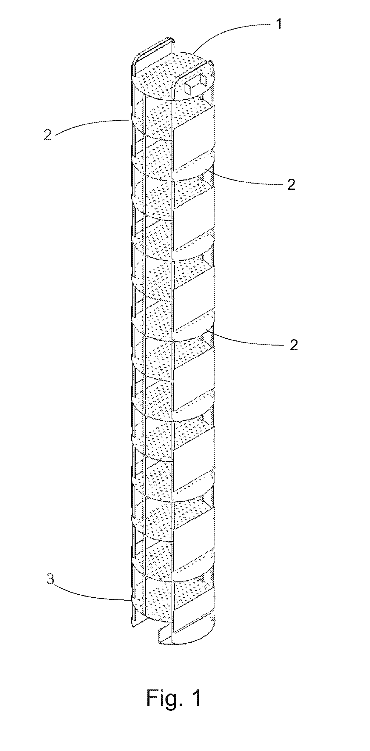
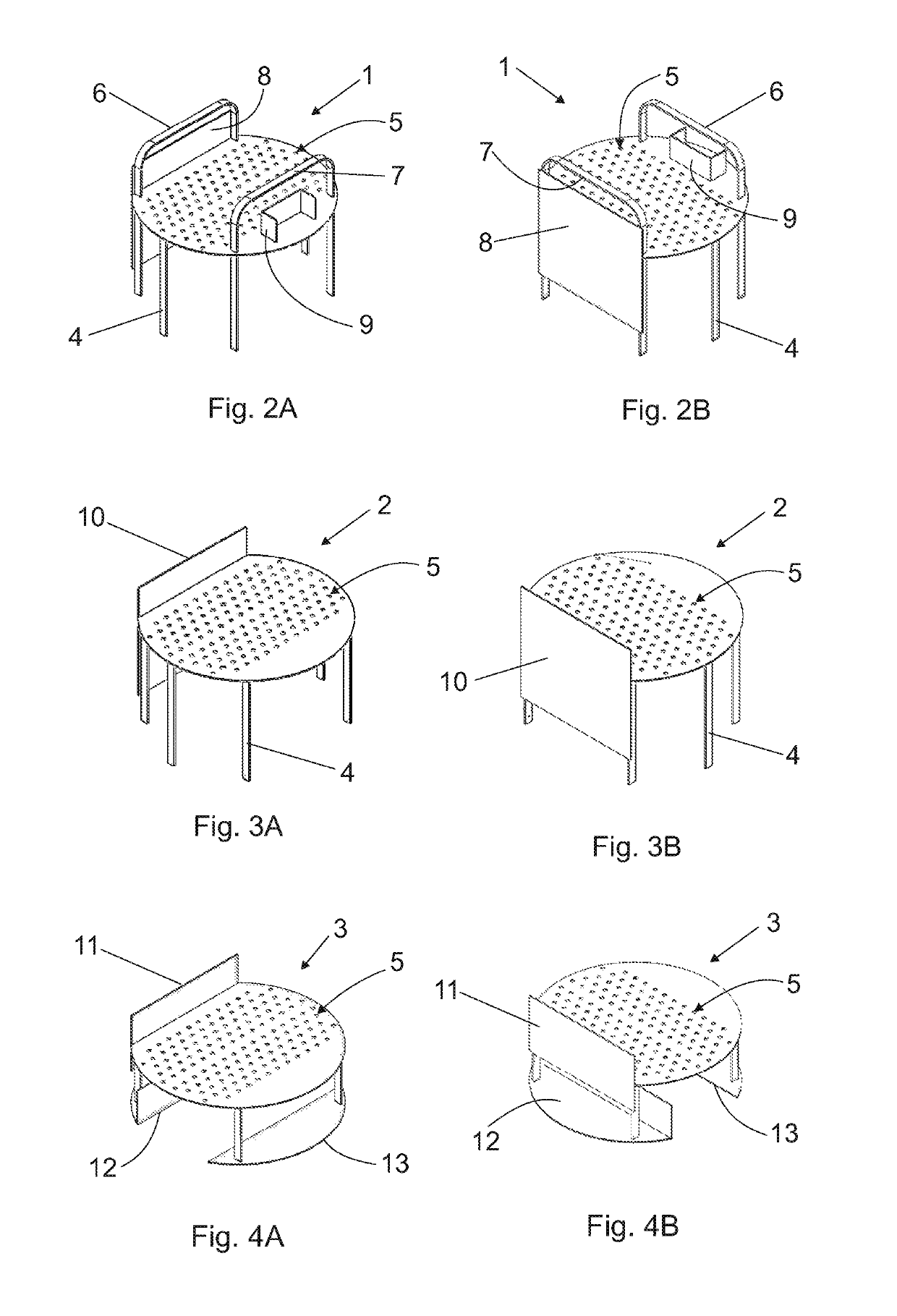
[0042]FIG. 1 shows a wort column formed by a succession of perforated plates, detachable superimposed one on top of the other, comprising an upper plate 1, a plurality of intermediate plates 2, and a lower plate 3, which are housed in a tube (not shown) defining the housing of the section column according to the diameter of the set of plates to be housed. The plates are spaced from each other by means of respective vertical panels 4 defining perimeter support legs and, at the same time, are structural reinforcements which keep the succession of superimposed plates aligned. Each of said upper 1, intermediate 2 and lower 3 plates has a plurality of perforations 5, for example in an amount of 134 perforations per plate.

[0043]In FIGS. 2A and 2B it can be seen that the upper plate 1 has inverted “U” shaped supports 6 and 7, from which it is secured to proceed to the removal of the set of plates. The side arms of said supports 6 and 7 are aligned with the corresponding panels 4 in order t...


PUM

PropertyMeasurementUnit
shapeaaaaaaaaaa
perimeteraaaaaaaaaa
timeaaaaaaaaaa

Abstract

Improvements in grain alcohol distillation plants by incorporating a novel internal arrangement in the wort column and the rectifying column with distributors and accumulators inside thereof, achieving a stable and safe process in wide ranges of operation, guaranteeing the productivity of the plant and the quality of the products. The wort column features detachable perforated plates, easy to access and clean through manholes. By having easily detachable plates and, also, a manhole for each plate with “holder” type connections, the access to the interior of the column for cleaning and maintenance purposes is facilitated. The rectifying column is a special filling column with flow distributors, it has an intermediate alcohol accumulator and a condenser which is an integral part of the column that prevents the use of pumps. The arrangement of distributors and accumulators within the rectifying column favors the operational stability of the plant, allowing a low scale equipment to work similarly to an industrial scale column. The improvements include an integrated automation system with Internet communication for self-management of the plant with remote monitoring and autonomous operation.

Description

FIELD OF THE INVENTION[0001]The present invention refers to improvements in grain alcohol distillation plants, and more particularly the invention refers to small grain ethanol production plants intended to be installed in agricultural establishments which can produce hydrated, anhydrous or high quality (potable) alcohol from different grains like corn, sorghum, rice, etc. By-products derived from the production of alcohol are, for example, moist distilled grains known as wet distillers grains, with high protein value, and a liquid food with high nutritional value as a source of energy. Wet distillers grains may at the same time undergo a drying process by the optional incorporation of a drying module in the plant, hereinafter referred to as “minidest”. In addition, it should be mentioned that the distillation plant with the improvements according to the present invention may be coupled to a biogas production plant which reuses the liquid feed stream in the generation thereof and, t...

Claims


Application Information

Patent Timeline
Patent Type & Authority Patents(United States)
IPC IPC(8): B01D3/42B01D5/00B01D3/32B01D3/14B01D1/08B01D1/10B01D3/00
CPCB01D3/001B01D1/08B01D1/10B01D3/002B01D3/14B01D3/42B01D5/003B01D5/006B01D5/0012B01D5/0063B01D3/326Y02E50/17Y02E50/10
Inventor PORTA, JOSE VICENTE RAMON
Owner PORTA HNOS SA
Learn More