Continuously variable transmission and method of controlling it

a transmission and continuously variable technology, applied in the direction of gearing control, gearing elements, gearing rings, etc., can solve the problems of insufficient sensor space, inability to accurately control the speed of the variable, and large system size, so as to reduce the axial length of the transmission and reduce the width of the engine section. , the effect of flexible layout design

Inactive Publication Date: 2005-02-17
YAMAHA MOTOR CO LTD
View PDF0 Cites 162 Cited by
  • Summary
  • Abstract
  • Description
  • Claims
  • Application Information

AI Technical Summary

Benefits of technology

[0104] If the continuously variable transmission is applied to motorcycles, as has been described, there exists an overlapping area where the slide range of the slide drive means coupled to the motor and the slide range of the movable sheave axially moved by the slide drive means overlaps each other, thereby to reduce the axial length of the transmission. Accordingly, if the transmission is located so that the axis of t

Problems solved by technology

In such a constitution utilizing the centrifugal force of the weights as described above, it is difficult to obtain uniform centrifugal force and to regulate finely, resulting in inaccurate variable speed control.
Accordingly, it is required to secure spaces near the rotational shaft for installation of the motor and transmission gears, resulting in a larger size of the whole system.
As a result, a space for the sensor is also required, and the number of parts and the cost will be increased.
In order to always hold the movable sheave at a predetermined position against the thrust force, it is necessary to provide a complicated speed reduction mechanism, such as a planetary gear mechanism between the movable sheave and the motor shaft, or to always energize the motor for generating torque against the thrust force, resulting in a larger size of the mechanisms and the increase of consumption power.
Such a transmission described above has however possibilities to cause the accuracy of parts or components and reliability to be

Method used


Image

  • Continuously variable transmission and method of controlling it
  • Continuously variable transmission and method of controlling it
  • Continuously variable transmission and method of controlling it

Examples


Embodiment Construction

[0110] Embodiments of the invention will be described below with reference to the accompanying drawings.

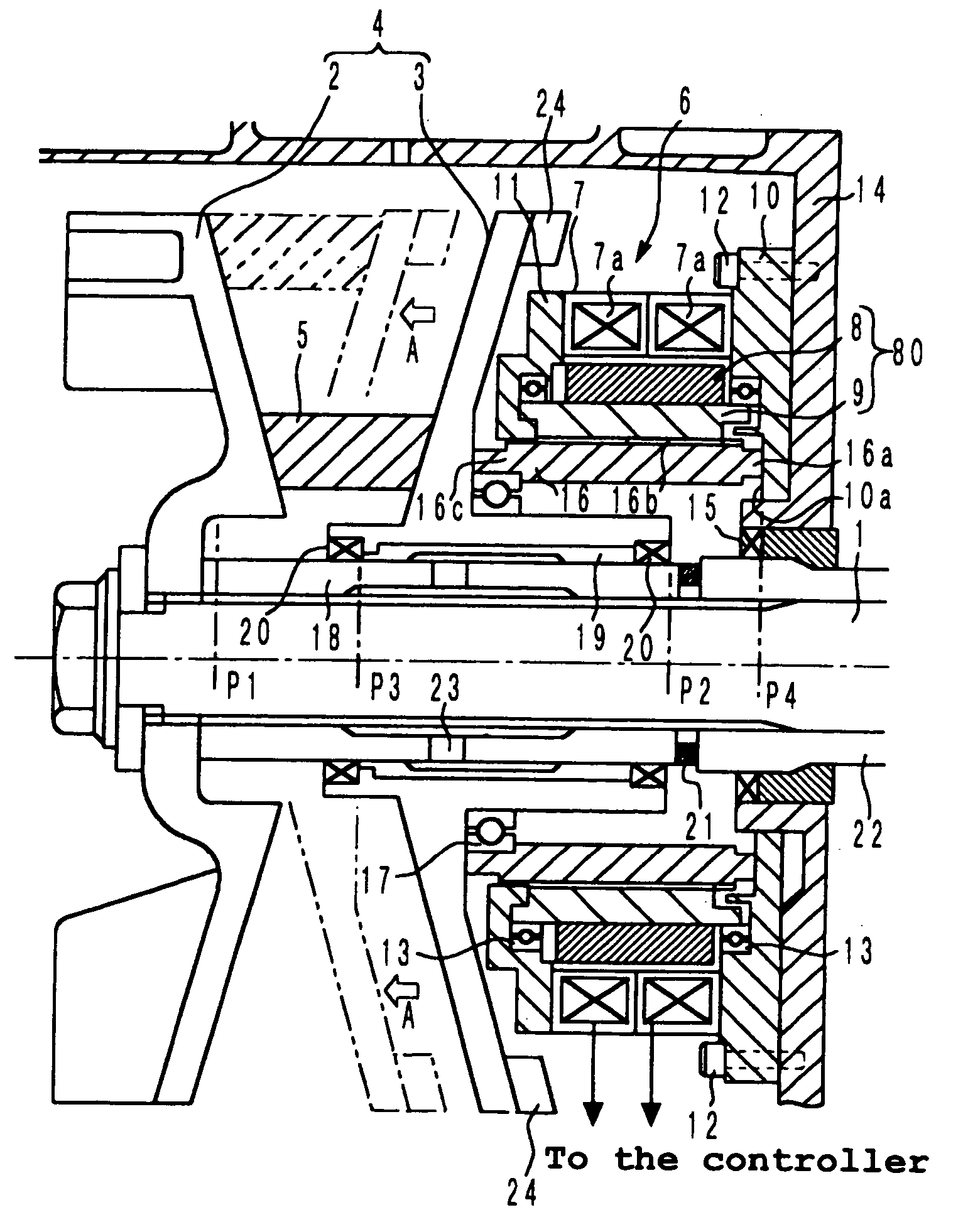
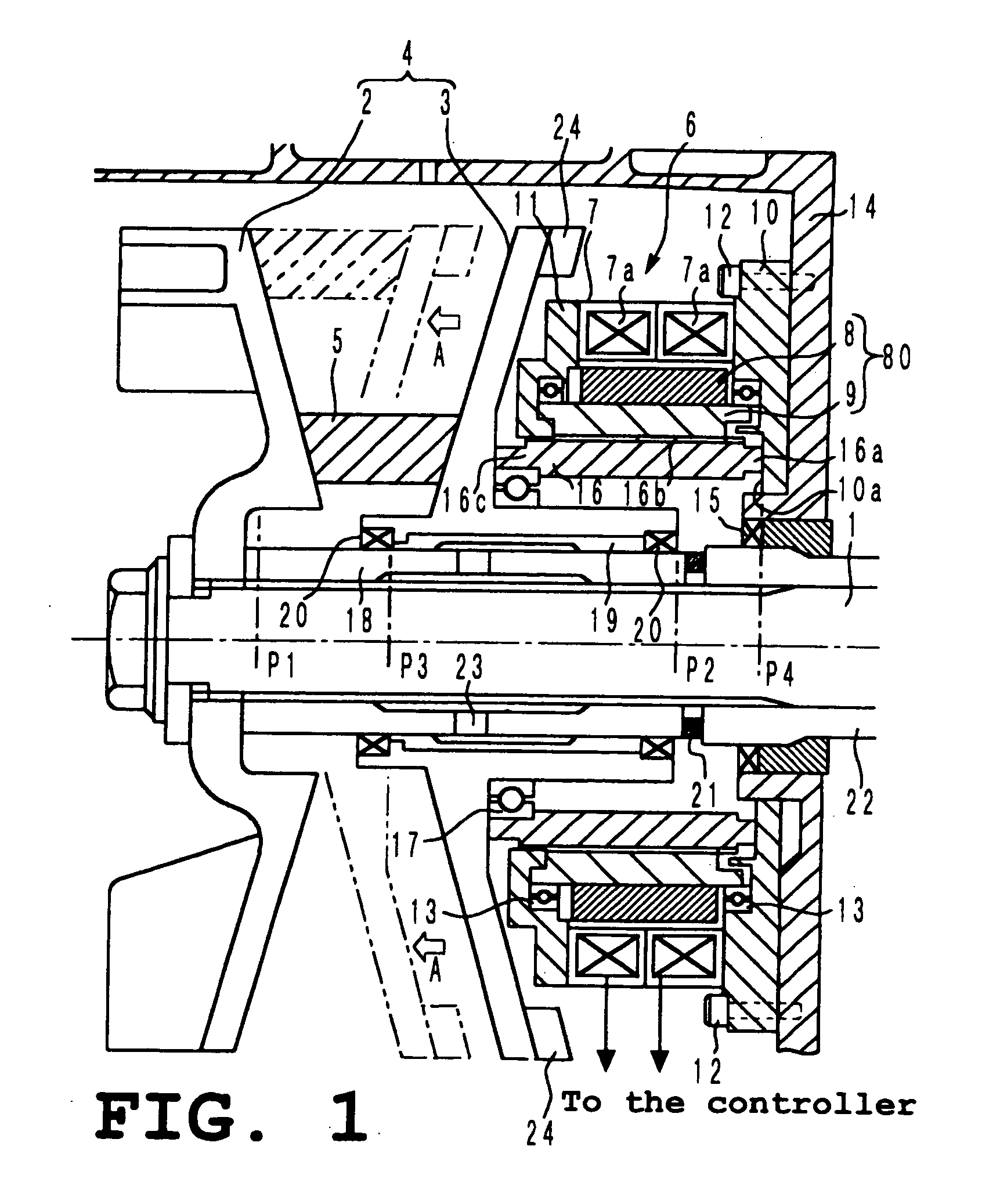
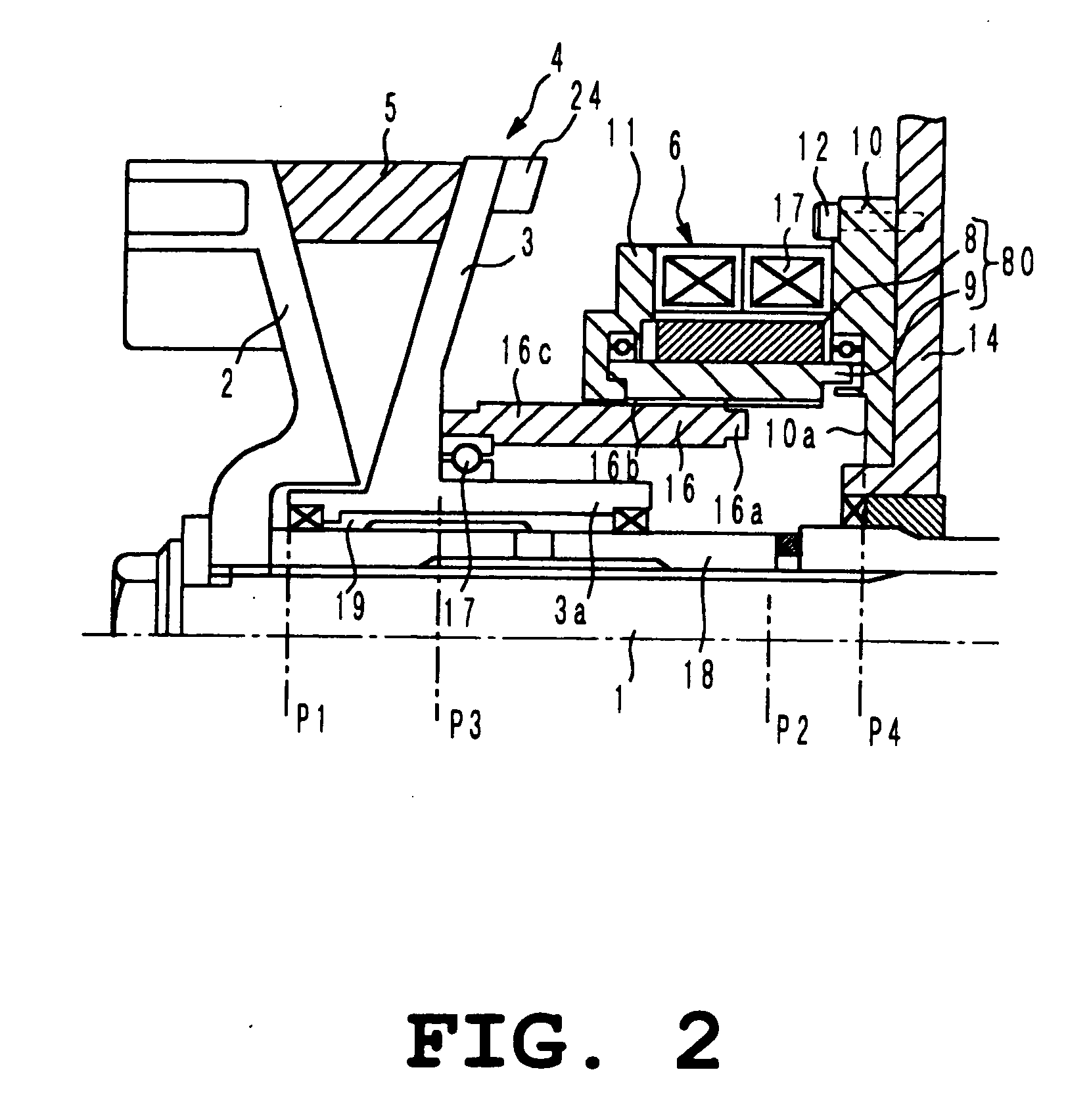
[0111]FIG. 1 shows a constitution of a portion of a CVT related to an embodiment of the invention. FIG. 2 shows a constitution of a portion of the continuously variable transmission of FIG. 1, explaining its action.

[0112] On an engine output shaft 1 is mounted a primary sheave (drive side sheave) 4 consisting of a pair of opposed fixed sheave 2 and movable sheave 3. The fixed sheave 2 and the movable sheave 3 are formed in a conical shape at their opposed surfaces. Between these opposed conical surfaces is mounted a V-belt 5. A driven shaft (not shown) connected to an axle, for example, is provided in parallel with the engine output shaft 1, and this driven shaft is also provided with a secondary sheave (driven side sheave) consisting of a pair of fixed sheave and movable sheave. The V-belt 5 is wound over the primary sheave 4 and the secondary sheave (not shown), and variable s...


PUM


Abstract

To provide a continuously variable transmission and a control method thereof, allowing for control of the axial position of a movable sheave without a sensor for measuring the axial position of the movable sheave on a rotational shaft and for stable control with the movable sheave being held in position, without the increase in the size of mechanisms and power consumption.
A continuously variable transmission in which, on a rotational shaft 1 thereof are mounted a fixed sheave 2 positioned in the axial direction and a movable sheave 3 slidable axially, so as to face each other, a motor is provided for driving the movable sheave, and a slide driving means 16 is provided for sliding the movable sheave 3 axially by the rotation of the motor, characterized in that: the motor is a step motor 6, and the step motor 6 and the slide drive means 16 are mounted coaxially with the rotational shaft 1.

Description

TECHNICAL FIELD [0001] This invention relates to a belt-type continuously variable transmission (CVT) installed in, for example, an engine for an automobile and a motorcycle, for transmitting the driving force from the engine to a driven axle and also relates to a control method thereof. BACKGROUND ART [0002] In a continuously variable transmission for a vehicle or the like, a pair of sheaves (that is, a primary sheave on the driving side and a secondary sheave on the driven side) are mounted on a rotational shaft on the driving side and the driven side, respectively and an endless V-belt is bridged between both sheaves to couple both sheaves. Of the two sheaves, one is a fixed sheave that is axially positioned and the other is a movable sheave that can slide axially, both which are in turn mounted to the rotational shaft so as to face each other. Since the two opposite faces of a pair of the fixed and movable sheaves are tapered (in a conical shape), the radial distance of the endl...

Claims


Application Information

Patent Timeline
IPC IPC(8): F16H9/18F16H9/00F16H61/662F16H63/06
CPCF16H61/66254F16H2061/283F16H63/067F16H63/062
Inventor UNNO, TOSHIOHINO, HARUYOSHITAKEBE, MITSUKAZU
Owner YAMAHA MOTOR CO LTD
Why Eureka
Try Eureka