
Reconfigurable organic light-emitting device and display apparatus employing the same

Active Publication Date: 2005-02-24
NAT TAIWAN UNIV
View PDF6 Cites 89 Cited by
  • Summary
  • Abstract
  • Description
  • Claims
  • Application Information

AI Technical Summary

Benefits of technology

[0009] To solve the above mentioned problems, the primary objective of the present invention is to provide a reconfigurable organic light-emitting device, which is applicable to the fabrication of flat panel display and is capable of simplifying the manufacturing process of multi-color / full-color displays.
[0010] Another objective of the present invention is to provide a reconfigurable organic light-emitting device, the internal structure of which is reconfigurable by means of heating so as to control the color emitted by the reconfigurable organic light-emitting device.

Problems solved by technology

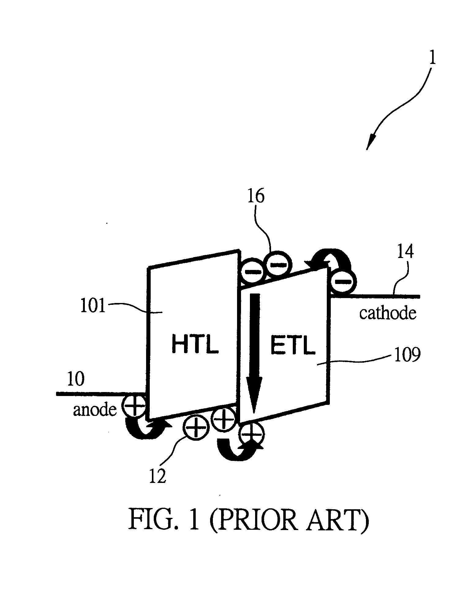
However, the operation voltage was so high that it is not applicable to a flat panel display.
However, the employment of this method would encounter problems such as shadow-mask alignment errors, vapor deposition shadowing errors during vapor deposition, difficulties in fabricating shadow masks with small openings, insufficient mechanical strength in large-area shadow masks, and the cleaning of the masks.
These problems will reduce the resolutions and yields of the display fabricated with this method.
However, the employment of this method would encounter the problems of complicated manufacturing processes and unsatisfactory yield of the fabricated displays.
However, the intensity of the light obtained through the color filter, in accordance with this method, would lose more than two thirds of that of the white light emitted by the organic light-emitting device.
Thus, the light-emitting efficiency would be largely reduced if the display were fabricated with this method.
However, the display of the organic light-emitting device fabricated with this method would encounter the problem of energy conversion efficiency due to the light conversion layer.

Method used


Image

  • Reconfigurable organic light-emitting device and display apparatus employing the same
  • Reconfigurable organic light-emitting device and display apparatus employing the same
  • Reconfigurable organic light-emitting device and display apparatus employing the same

Examples


example

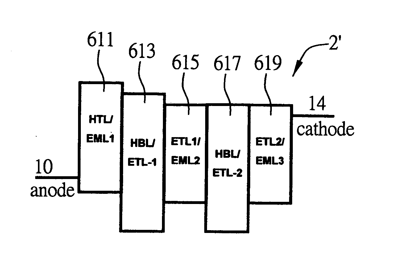
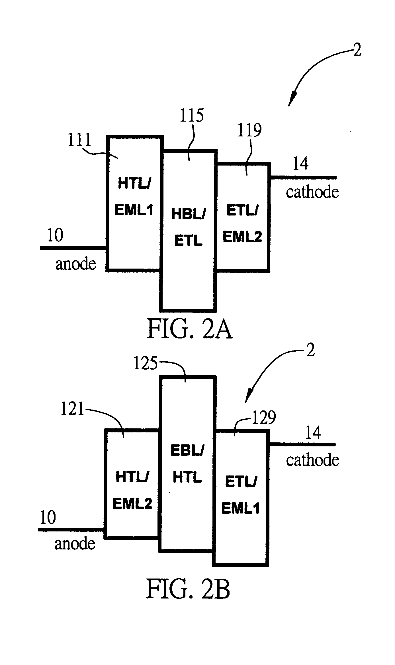
[0098] Referring now to FIG. 17, a cross-sectional view of a reconfigurable organic light-emitting device 4 having a light-to-heat conversion layer is illustrated. The reconfigurable organic light-emitting device 4 having a light-to-heat conversion layer comprises a glass substrate 1200 coated with ITO as a lower electrode, a layer of polyethylene dioxythiophene / polystyrene sulphonate (PEDT:PSS; see FIG. 18a) with a thickness of 300 Å deposited on the glass substrate 1200 coated with ITO as a hole injection layer 1202, a layer of ter(9,9′-spirobifluorene) (T-Spiro; see FIG. 18b) with a thickness of 400 Å deposited on the hole injection layer 1202 as a hole-transport / first light-emitting layer 1211, a layer of 2,9-dimethyl-4,7-diphenyl-1,10-phenanthroline (BCP; see FIG. 18d) with a thickness of 75 Å deposited on the hole-transport / first light-emitting layer 1211 as a hole-blocking / electron-transport layer 1215, a layer of tris-(8-hydroxyquinoline)aluminum (Alq; see FIG.18c) with a th...


PUM


Abstract

A reconfigurable organic light-emitting device and the display apparatus employing such organic light-emitting device, wherein the reconfigurable organic light-emitting device comprises at least two organic light-emitting layers and at least one high-energy-gap carrier-blocking layer. The at least one high-energy-gap carrier-blocking layer is formed between each of the organic light-emitting layers. The structure of the reconfigurable organic light-emitting device can be reconfigured through heating, and the reconfigurable organic light-emitting device may thus emit light characteristic of one layer of the at least two organic light-emitting layers, after a bias voltage is applied on the upper electrode and the lower electrode of the reconfigurable organic light-emitting device. The heating may be performed with a built-in resistive heating source, an external heating source or a light-beam. By employing the reconfigurable organic light-emitting device, fixed-pattern, passive-matrix, and active-matrix display apparatus of multi-color or full-color may further be fabricated.

Description

FIELD OF THE INVENTION [0001] This invention relates to generally organic light-emitting devices and display apparatus which employs the same, and, more specifically, to a reconfigurable organic light-emitting device and a display apparatus which employs the reconfigurable organic light-emitting device. BACKGROUND OF THE INVENTION [0002] The earliest organic light-emitting device (OLED) was proposed, in 1963, by Pope et al, who applied a 1000 V voltage to both ends of an anthracene crystal with a thickness of 1 mm and observed light emission. However, the operation voltage was so high that it is not applicable to a flat panel display. The structure and the manufacturing method of the organic light-emitting device nowadays were proposed by C. W. Tang and S. A. VanSlyke of the Eastman Kodak Company. One may manufacture the structure by sequentially depositing non-crystalline thin films of organic materials, with vacuum deposition on a glass substrate that is precoated with a transpare...

Claims


Application Information

Patent Timeline
IPC IPC(8): H01L27/32H01L35/24H01L51/50H01L51/52
CPCH01L27/3211H01L51/529H01L51/5096H01L51/5036H10K59/35H10K50/125H10K50/18H10K59/8794H10K50/87
Inventor WU, CHUNG-CHIHCHEN, CHIEH-WEICHO, TING-YI
Owner NAT TAIWAN UNIV
Learn More