Projection optical system and optical system

a technology of optical system and optical system, applied in the field of projection optical system, can solve the problems of difficult to ensure high optical performance, difficult to incline an image plane sufficiently, and difficulty in manufacturing the optical system with high precision, and achieve the effect of reducing size and reducing distortion

Inactive Publication Date: 2005-02-24
CANON KK
View PDF30 Cites 27 Cited by
  • Summary
  • Abstract
  • Description
  • Claims
  • Application Information

AI Technical Summary

Benefits of technology

The present invention has been made in consideration of the above situation, and has as its object to provide an oblique projection or incidence type optical system which attains a reduction in size and has little distortion.

Problems solved by technology

In the optical system disclosed in Japanese Patent Application Laid-Open No. 5-80418, since the lens system is simply tilted, it is difficult to incline an image plane sufficiently.
In addition, if the tilt amount of the lens system is excessively large, it is difficult to ensure high optical performance.
WO97 / 01787, one reflecting surface increases in size, resulting in difficulty in manufacturing the optical system with high precision.
As disclosed in Japanese Patent Application Laid-Open No. 6-295159, in the method of displaying an image by scanning a point light source or one-dimensional image display element with a rotating polyhedral mirror or galvano mirror, distortion may not satisfactorily be corrected by electrical correction alone.

Method used


Image

  • Projection optical system and optical system
  • Projection optical system and optical system
  • Projection optical system and optical system

Examples


first embodiment

(First Embodiment)

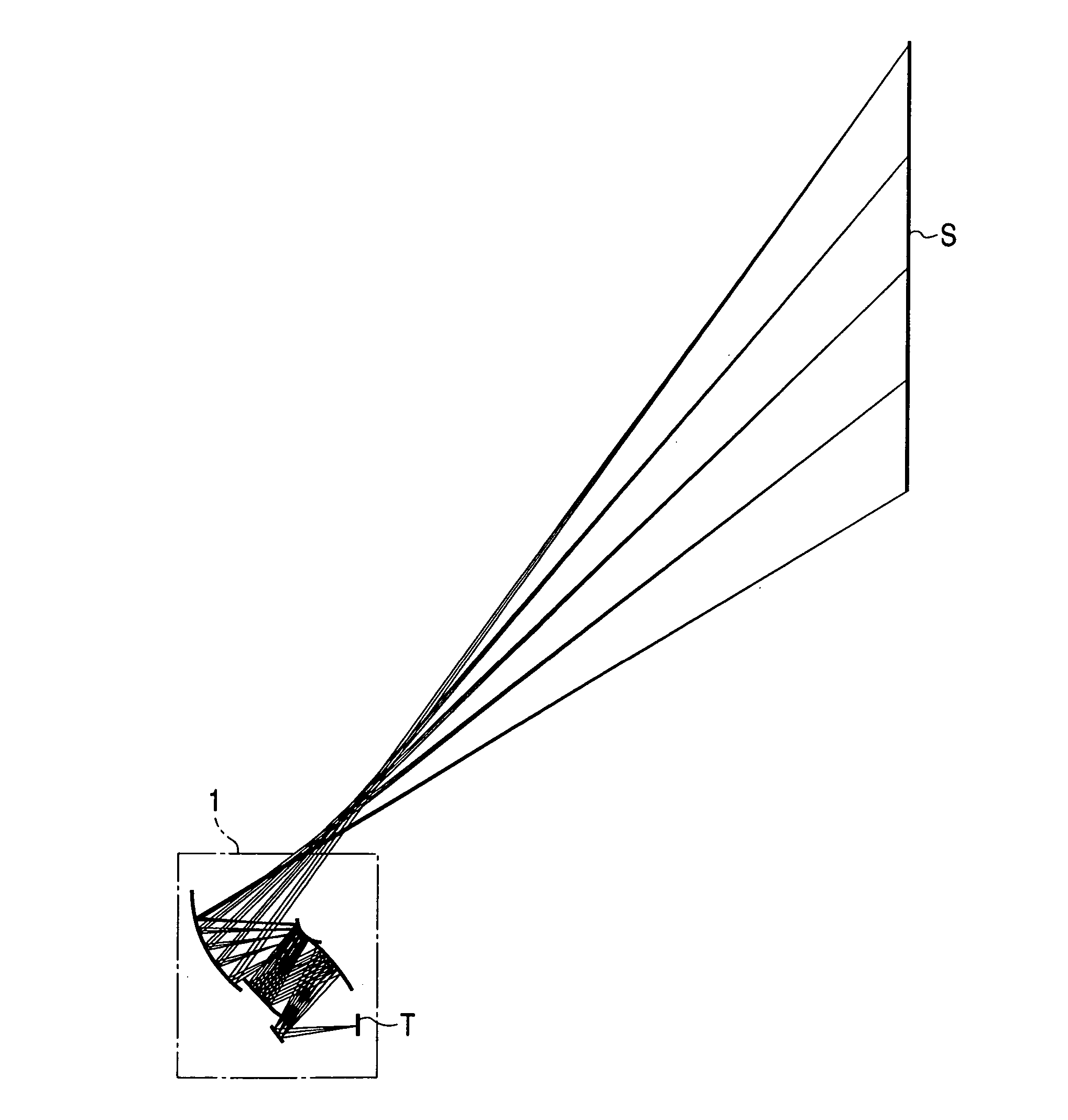
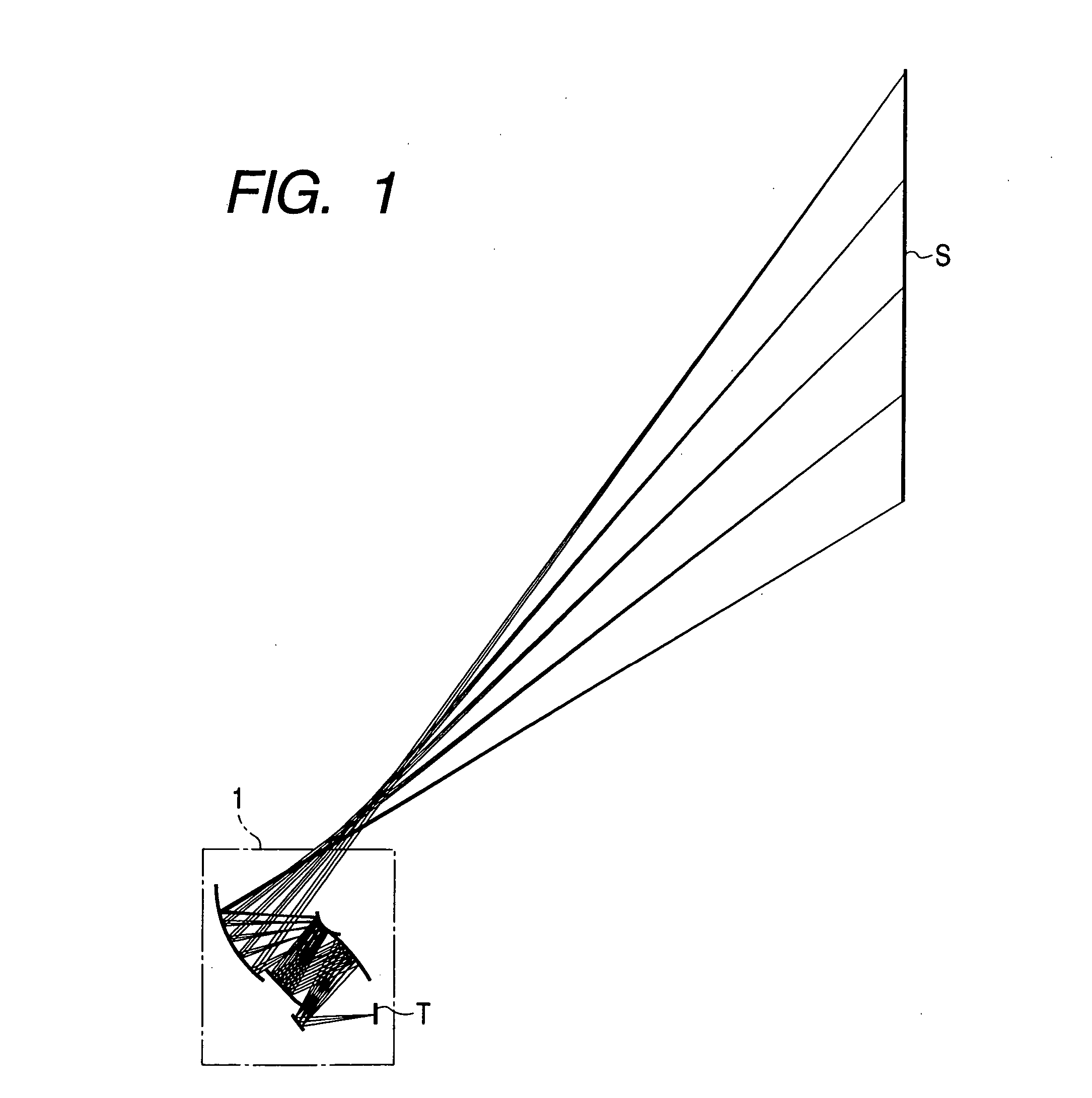
FIG. 1 shows an image projection apparatus according to the first embodiment of the present invention. Referring to FIG. 1, as a one-dimensional optical modulation unit T, a self-emission device which can modulate an emission intensity of a light-emission diode, semiconductor laser, or the like can be used. Instead of such a self-emission device, a unit including a light valve using a dot matrix liquid crystal panel or mirror device and a lighting system for causing illumination light strike the light valve may be used.

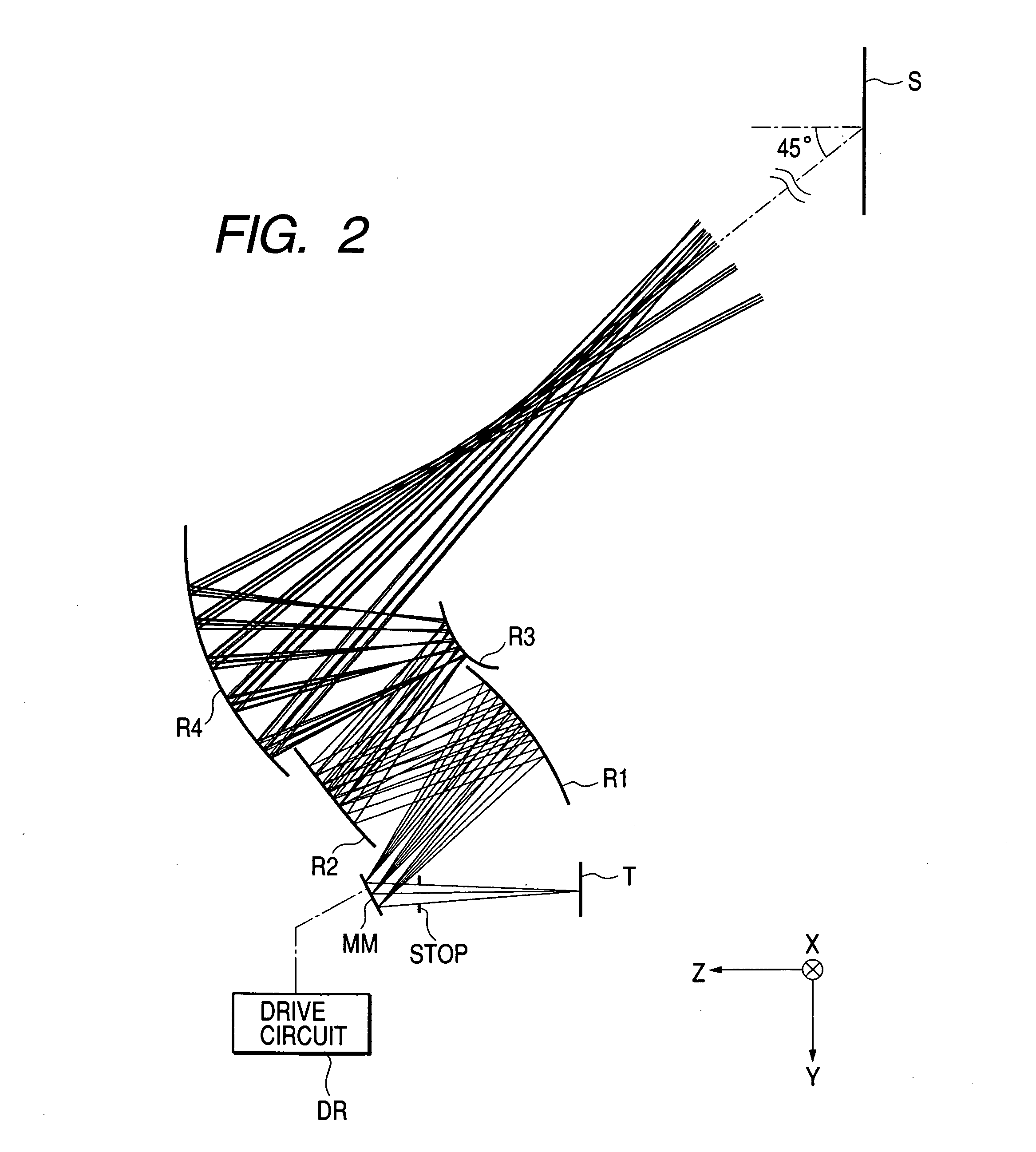
A projection optical system 1 is used to enlarge / project an image formed by the optical modulation unit T onto a screen (projected surface) S. FIG. 2 shows the arrangement of this system in more detail.

The projection optical system 1 includes a stop STOP and an optical scanning unit MM such as a galvano mirror or rotating polyhedral mirror.

The length of the optical modulation unit T in the Y-axis direction is 8 mm. The screen S has an aspect ra...

second embodiment

(Second Embodiment)

FIG. 5 shows the arrangement of an image projection apparatus according to the second embodiment of the present invention. Referring to FIG. 5, as a one-dimensional optical modulation unit T, a self-emission device which can modulate an emission intensity of a light-emission diode, semiconductor laser, or the like can be used. Instead of such a self-emission device, a unit including a light valve using a dot matrix liquid crystal panel--or mirror device and a lighting system for causing illumination light strike the light valve may be used.

A projection optical system 2 is used to enlarge / project an image formed by the optical modulation unit T onto a screen (projected surface) S. FIG. 6 shows the arrangement of this system in more detail.

The projection optical system 2 includes a refractive lens group LG and an optical scanning unit MM such as a galvano mirror or rotating polyhedral mirror, which also serves as a stop.

The length of the optical modulation uni...

third embodiment

(Third Embodiment)

FIG. 9 shows the arrangement of an image projection apparatus according to the third embodiment of the present invention. Referring to FIG. 9, as an optical modulation unit T having a point light source, a self-emission device which can modulate an emission intensity of a light-emission diode, semiconductor laser, or the like can be used. Instead of such a self-emission device, a unit including a light valve using a dot matrix liquid crystal panel or mirror device and a lighting system for causing illumination light strike the light valve may be used.

A projection optical system 3 is used to enlarge / project an image formed by the optical modulation unit T onto a screen (projected surface) S. FIG. 10 shows the arrangement of this system in more detail.

The projection optical system 3 includes a refractive lens group LG and an optical-scanning unit MM such as a galvano mirror or rotating polyhedral mirror, which also serves as a stop. In addition, the scanning dire...


PUM

PropertyMeasurementUnit
angleaaaaaaaaaa
distanceaaaaaaaaaa
field angleaaaaaaaaaa

Abstract

A projection optical system includes an optical modulation unit which outputs modulated light for displaying an image, an optical scanning unit on which the modulated light output from the optical modulation unit is incident, the optical scanning unit scanning the light from the optical modulation unit to obtain a two-dimensional image, and a plurality of curved reflecting surfaces on which the light scanned by the optical scanning means is sequentially incident, the plurality of curved reflecting surfaces sequentially reflecting the light scanned by the optical scanning means and projecting the light on a projected surface, wherein when an optical path of a ray connecting a center of a pupil of the projection optical system and a center of a projected image is set as a reference axis, the reference axis is inclined with respect to a normal to the projected surface.

Description

BACKGROUND OF THE INVENTION 1. Field of the Invention The present invention relates to a projection optical system for obliquely projecting a two-dimensional image formed by scanning light from a light source and an optical system suitable for oblique projection or oblique image pickup. 2. Description of the Related Art As a projection optical system used for a forward projection type projector, a projection optical system capable of obliquely projecting an image on a screen to shorten the distance between the screen and an apparatus has been proposed. FIG. 13 shows a projector disclosed in Japanese Patent Application Laid-Open No. 5-100312. Referring to FIG. 13, this projector includes an illumination light source L and a light valve LV using a reflection dot matrix liquid crystal device or the like. A projection optical system enlarges and projects an image formed on the light valve LV onto a screen S. In this projector, a wide-angle lens having a large field angle is used as ...

Claims


Application Information

Patent Timeline
Patent Type & Authority Applications(United States)
IPC IPC(8): G02B17/06G02B17/08G02B27/18G02F1/13G03B21/00G03B21/14H04N5/74H04N9/31H04N17/00
CPCG02B17/0663G02B17/0848H04N9/3129H04N5/74G02B17/0852
Inventor SUNAGA, TOSHIHIRO
Owner CANON KK
Why Eureka
Try Eureka