Wavelength division multiplexing transmission system

a transmission system and wavelength division technology, applied in wavelength-division multiplex systems, multiplex communication, electromagnetically repeaters, etc., can solve the problems of increasing cost, requiring higher performance and specifications, and difficulty in upgrading an arbitrary channel to 40 gbit/s, etc., to achieve high function devices, high performance, and cost reduction

Inactive Publication Date: 2005-02-24
FUJITSU LTD
View PDF4 Cites 12 Cited by
  • Summary
  • Abstract
  • Description
  • Claims
  • Application Information

AI Technical Summary

Benefits of technology

[0020] Therefore, in the first demultiplexing unit or in the first demultiplexing, a high performance and high function device can be used for the device which is appropriate for processing the first signal lights (e.g. signal band is large (bit rate is high)), only in the portion where the first signal light is included in the first channel group, and in the portion where the second channel group (second signal lights included in the first channel) is processed, a device which is appropriate for processing the second signal lights, which is different from the first signal lights, can be used. By this, a wavelength division multiplexing transmission system where signal lights with different bit rates are mixed, keeping cost down, can be provided. Also a wavelength division multiplexing transmission system where signal lights with different bit rates are mixed, keeping a cost increase caused by high function devices and various compensation devices down, can be provided. Since the first signal light and the second signal light can be individually processed, a wavelength and polarization mode dispersion compensation method, which are optimum for the respective bit rate, can be applied.

Problems solved by technology

Therefore it is difficult to upgrade an arbitrary channel to 40 Gbit / s.
Therefore the device for 40 Gbit / s requires higher performance and higher specifications, which increases cost.
In other words, the multiplexer / demultiplexer for high-speed has high performance using high specifications to decrease the Q factor deterioration, so the device cost is higher in the multiplexer / demultiplexer for high-speed.
Therefore it is not desirable to install a device for 40 Gbit / s for all the channels in terms of cost, and using a 40 Gbit / s device for 10 Gbit / s signals exceeds specifications, which also generates an unnecessary cost.

Method used


Image

  • Wavelength division multiplexing transmission system
  • Wavelength division multiplexing transmission system
  • Wavelength division multiplexing transmission system

Examples


embodiment 1

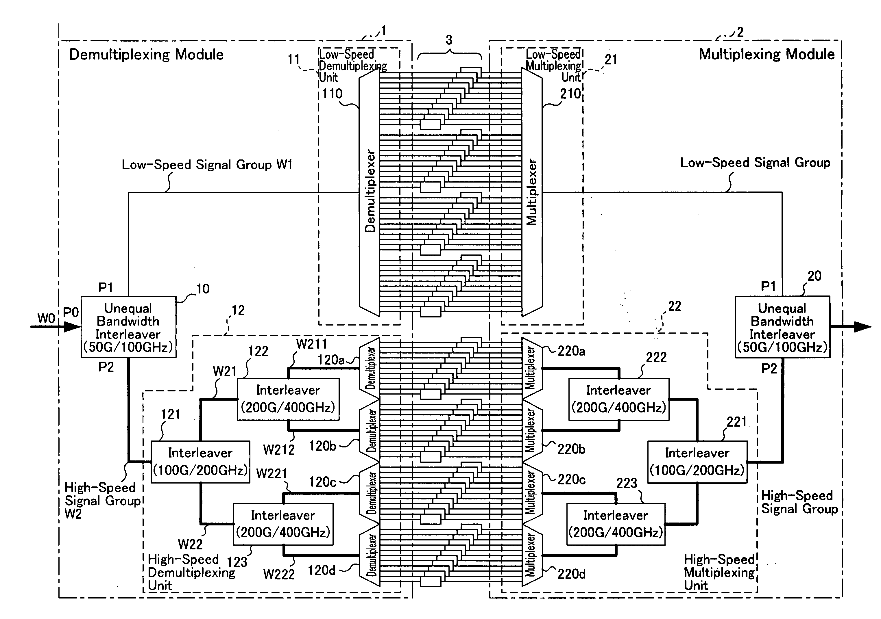
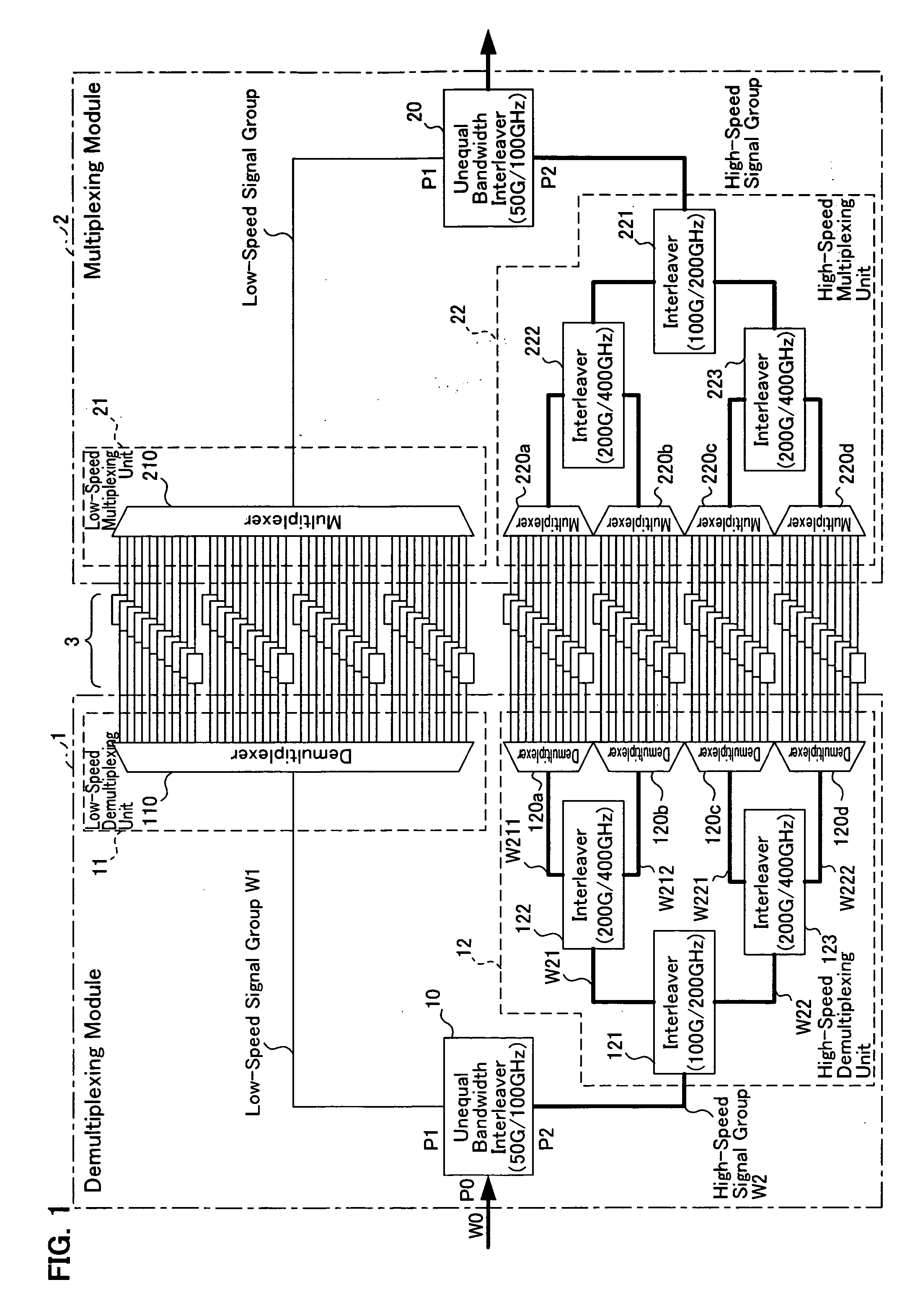
[0060]FIG. 1 is a block diagram depicting the configuration of the optical transmission node according to the first embodiment of the present invention. This optical transmission node is a relay node which is installed in the wavelength division multiplexing (WDM) transmission system, and is comprised of a demultiplexing module 1 and a multiplexing module 2. In the present embodiment, the relay node will be described as an example, but the present invention can be applied not only to the relay node of the WDM transmission system but also to the transmission terminal or the reception terminal of the WDM transmission system. For example, in the transmission terminal, only the multiplexing module 2 is installed, and in the reception terminal, only the demultiplexing module 1 is installed. The present invention can be applied to the transmission terminal or the reception terminal in this way, which is the same for the second to twelfth embodiments herein below.

[0061] The demultiplexing...

embodiment 2

[0095]FIG. 5 is a block diagram depicting the configuration of the optical transmission node according to the second embodiment of the present invention. This optical transmission node comprises a demultiplexing module 1a and a multiplexing module 2a.

[0096] The demultiplexing module 1a is comprised of an unequal bandwidth interleaver 10a, low-speed demultiplexing unit 11a, and high-speed demultiplexing unit 12a. The low-speed demultiplexing unit 11a is further comprised of multiplexers for low-speed signals 110a and 110b. The high-speed demultiplexing unit 12a is further comprised of interleavers for highs-speed signals 122 and 123, and demultiplexers for high-speed signals 120a through 120d. The interleavers 122 and 123 and the demultiplexers 120a through 120d are the same as those denoted with the same reference symbols in FIG. 1.

[0097] The multiplexing module 2a is comprised of an unequal bandwidth interleaver 20a, low-speed multiplexing unit 21a and high-speed multiplexing uni...

embodiment 3

[0141]FIG. 11 is a block diagram depicting the configuration of the optical transmission node according to the third embodiment of the present invention. This optical transmission node comprises a demultiplexing module 1b and a multiplexing module 2b.

[0142] The demultiplexing module 1b is comprised of an unequal bandwidth interleaver 10, low-speed demultiplexing unit 11b, and high-speed demultiplexing unit 12b. The low-speed demultiplexing unit 11b is further comprised of demultiplexers for low-speed signals 110 and 111. The high-speed demultiplexing unit 12b is further comprised of interleavers for high-speed signals 121 and 123, and demultiplexers for high-speed signals 120c and 120d. The multiplexing module 2b is comprised of an unequal bandwidth interleaver 20, low-speed multiplexing unit 21b, and high speed multiplexing unit 22b. The low-speed multiplexing unit 21b is further comprised of the multiplexers for low-speed signals 210 and 211. The high-speed multiplexing unit 22b ...


PUM


Abstract

The present invention provides a wavelength division multiplexing transmission system for separating wavelength division multiplexing signals, where signal lights with different bit rates are wavelength division multiplexed, according to the bit rate, and processing the separated signals individually. The wavelength division multiplexed signals, where a low-speed bit rate signal is disposed in an odd channel group and a high-speed bit rate signal is disposed in an even channel group, are demultiplexed into a low-speed signal group and a high-speed signal group by an unequal bandwidth interleaver. The low-speed signal group is processed (e.g. demultiplexing, dispersion compensation) by an optical device appropriate for the low-speed signals, and the high-speed signal group is processed by an optical device appropriate for the high-speed signals. By this, a relatively expensive and high function optical device can be applied only for the high-speed signal side, so an increase in the device cost can be kept down. Also a device with specifications appropriate for each signal can be used.

Description

BACKGROUND OF THE INVENTION [0001] 1. Field of the Invention [0002] The present invention relates to a wavelength division multiplexing transmission system for separating wavelength division multiplexing signals, where signal lights with different signal bandwidths (e.g. bit rates) are wavelength-division multiplexed, according to the signal bandwidth (bit rate), and processing separated signals individually and the relay node (compensating node) thereof. [0003] 2. Description of the Related Art [0004] Recently the capacity of Wavelength Division Multiplexing (WDM) transmission systems is expanding. Methods used for increasing capacity are increasing the number of wavelengths to be multiplexed and are increasing the transmission speed (bit rate) of signals with each wavelength. Concerning the bit rate, WDM transmission systems with 10 Gbit / s have already been commercialized, and research and development of optical transmission systems with 40 Gbit / s are on-going. [0005] To install 4...

Claims


Application Information

Patent Timeline
Patent Type & Authority Applications(United States)
IPC IPC(8): H04B10/2507H04J14/00H04B10/2525H04B10/2569H04B10/29H04B10/291H04J14/02
CPCH04J14/02H04J14/0227H04J14/0221
Inventor NAKAMURA, KENTAROOOI, HIROKIISHIKAWA, GEORGE
Owner FUJITSU LTD
Why Eureka
Try Eureka