Low friction planarizing/polishing pads and use thereof

a technology of low friction and planarizing, applied in the field of pads, can solve the problems of reducing the removal rate, reducing the efficiency of the process, so as to reduce the removal rate and reduce the friction of the process

Inactive Publication Date: 2005-02-24
IBM CORP
View PDF23 Cites 50 Cited by
  • Summary
  • Abstract
  • Description
  • Claims
  • Application Information

AI Technical Summary

Benefits of technology

[0043] An advantage of the present invention as compared to including solid lubricant particles in the slurry is that the friction of the process can be smaller than with slurries because larger amounts of solid lubricant particles can be incorporated into the pad material then into the slurry without reducing the removal rate to non-economical values.
[0044] An embodiment of a pad, suitable for the semiconductor industry, is a substantially cylindrical pad having general dimensions such that it might be used in a polishing apparatus, for example in the equipment described in the IBM Technical Disc

Problems solved by technology

The deviation from perfect planarity, referred to as a step, is detrimental due to depth-of-focus issues in subsequent lithography steps.
Also, this deviation in the case of oxide polish can lead to field threshold problems in isolation regions, while in the case of metal planarization can cause shorts in the next metal level.
Another obstacle of using solid lubricant

Method used


Image

  • Low friction planarizing/polishing pads and use thereof
  • Low friction planarizing/polishing pads and use thereof
  • Low friction planarizing/polishing pads and use thereof

Examples


example 1

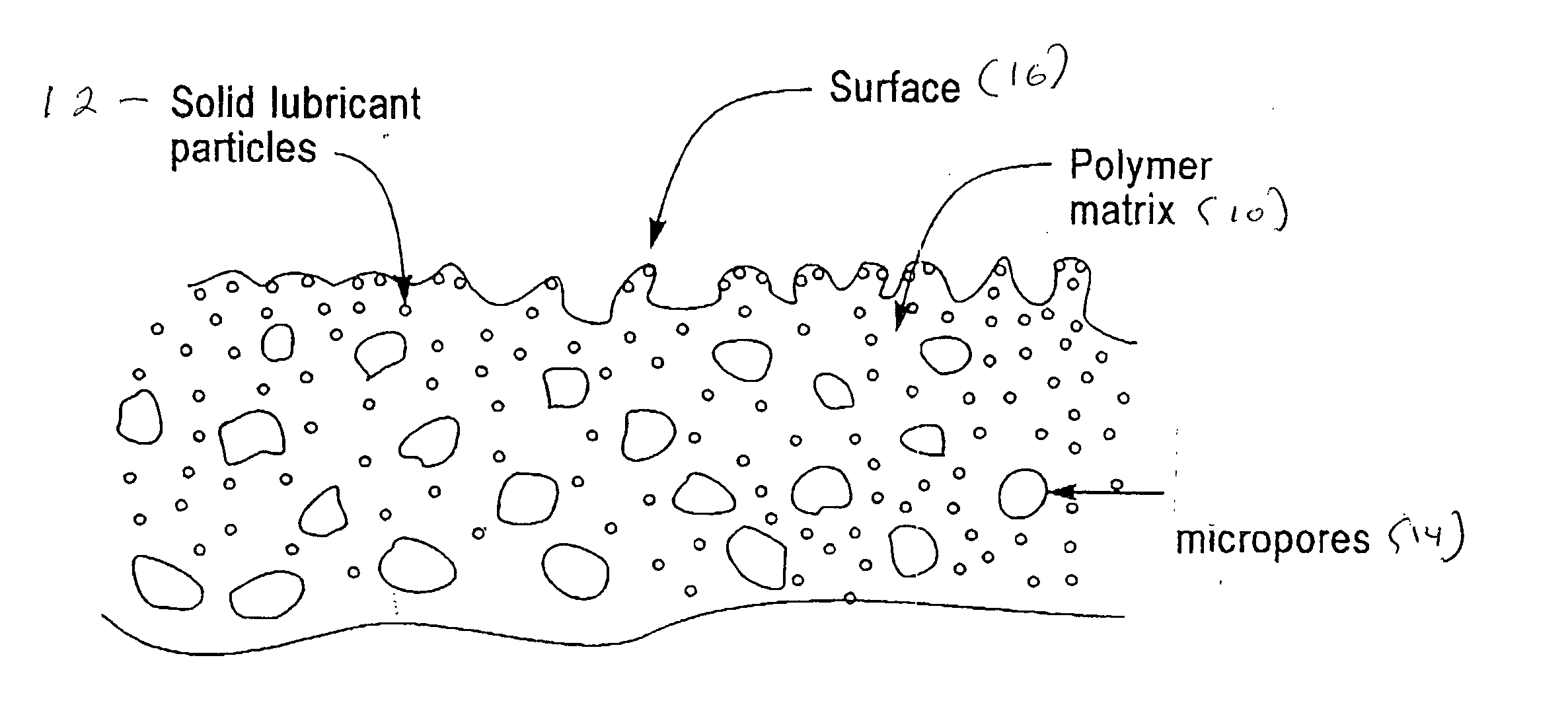
[0047] A porous polyurethane pad is provided according to the method in U.S. Pat. No. 5,900,164 by mixing liquid urethane with a polyfunctional amine at a proper temperature in the ratio required by the desired amount of cross-linking. During the “low viscosity window” hollow elastic polymeric microspheres are blended with the polymers mixture and 2% by weight of PTFE solid lubricant particles of 0.2 micron average diameter available under the trade name of Pinnacle 9003 by Carroll Scientific Inc., are blended applying a high shear rate mixer. The solid lubricant particles can be added to the liquid urethane or the liquid urethane-polyfunctional amine mixture, or the liquid urethane-polyfunctional amine-microspheres mixture.

[0048] The mixture is transferred during the low viscosity window to a convention mold and permitted to gel. It is subsequently cured in an oven, cooled and cut to form polishing pads. FIG. 3 shows the cross-section of a planarizing pad according to the present ...

example 2

[0050] In producing a non-porous pad the process of Example 1 is followed except that the hollow microspheres are not added. Thus a liquid urethane is mixed with a polyfunctional amine at a proper temperature in a ratio required by the desired amount of cross-linking. During the “low viscosity window” 3% by weight of PTFE solid lubricant particles of 0.2 micron average diameter with the trade name of Pinnacle 9003 by Carroll Scientific Inc. are blended into the liquid polymer mix applying a high shear rate mixer. The lubricant particles can be added into the liquid urethane, or into the liquid urethane-polyfunctional amine mixture.

[0051] The mixture is transferred during the low viscosity window to a conventional mold and permitted to gel. It is subsequently cured in an oven, cooled and cut to form a polishing pad. Since this pad does not transport slurry well a surface texture providing macroscopic channels for slurry transport is mechanically produced on the surface of the pad be...


PUM

PropertyMeasurementUnit
Percent by massaaaaaaaaaa

Abstract

A polishing pad comprising a polymeric matrix and solid lubricant particles is useful for planarizing surfaces, and preventing delamination and scratches.

Description

TECHNICAL FIELD [0001] The present invention relates to pads and use thereof. The pads are especially useful for planarizing and polishing surfaces in the microelectronics industry. More particularly the present invention relates to increasing the topological selectivity of planarizing / polishing pads by providing pads containing a polymeric matrix and solid lubricant particles. An added advantage of the pads of the present invention is that the reduced friction between the pads and surface being planarized / polished e.g.—wafer reduces delamination (peeling) due to planarization / polishing, which is particularly important in planarizing conductor lines embedded in low-k (i.e. low dielectric constant) insulators or porous low-k insulators or planarizing the insulators themselves. Furthermore, such pads reduce defects such as scratches. BACKGROUND OF THE INVENTION [0002] In microelectronics planarization metal or insulator layers are deposited conformally into etched trenches of a substr...

Claims


Application Information

Patent Timeline
IPC IPC(8): B24B37/04B24D3/32B24D3/34
CPCB24B37/24B24D3/346B24D3/32
Inventor RONAY, MARIA
Owner IBM CORP
Why Eureka
Try Eureka