
Solar powered sign annunciator

a sign and solar energy technology, applied in the direction of visible signalling systems, traffic control systems, instruments, etc., can solve the problems of catastrophic consequences, difficult maintenance, and expensive installation of notification attempts, and achieve the effect of reducing the number of attempts

Inactive Publication Date: 2005-03-03
BLYTH MR JOHN RANDOLPH
View PDF49 Cites 67 Cited by
  • Summary
  • Abstract
  • Description
  • Claims
  • Application Information

AI Technical Summary

Benefits of technology

[0005] It is an object of the present invention to provide a fully self-contained traffic sign with a day and night time annunciator lighting system that meet the design codes set forth in the Manual of Uniform Traffic Control Devices and other standards while avoiding the disadvantages of prior art.
[0006] It is another object of the present invention to produce a sign whose outward appearance retains the same familiar shape and look while providing visual enhancement upon vehicle approach 24 hours per day regardless of ambient lighting conditions.
[0007] It is still another object of the present invention to provide visual enhancement to the sign in such a manner that the major sign objectives as provided by the signage lettering, numbering or symbols are enhanced directly providing unequivocal direction to the driver.
[0008] It is still another object of the present invention to provide signage that can be field retrofit on existing sign posts and not require the use specialized installation techniques nor connections to the electric power grid.
[0009] It is further an object of the present invention to provide a new and improved annunciator traffic safety sign that is inexpensive to manufacture and easy to maintain and therefore cost effective to purchase to upgrade highway signage.
[0010] It is further still an object of the present invention to incorporate microprocessor control for all functions thereby allowing minimal solar cell requirements through the use of tightly controlled power usage and maximized charging with available sunlight up to latitudes of 45 degrees north and south.

Problems solved by technology

However, because of their common nature and ever-present appearance combined with other ordinary distractions that draw a driver's attention away from constant diligence, important safety signs are often missed, sometimes leading to catastrophic consequences.
Unfortunately most of these attempts at notification are either expensive to install and difficult to maintain or require a connection to a power source for the energy necessary to power a constantly flashing light.
Powered solutions also are expensive with the cost of electricity always a present factor.
Neither approach provides any appreciable forward direction light output capable of high visibility and hence fail to provide the attention capturing aspect associated with a bright, flashing light directed towards the driver and not the sign fascia and in particular neither provides any notification of sign approach during daylight hours.
Further U.S. Pat. No. 6,407,675 B1 to Mumford et. al. while disclosing a light utilizing a flashing light including an LED fails to address the need for high visibility by incorporating high intensity LEDs along with a plurality of LEDs necessary to attract attention and fails to provide for adequate power control to be able to operate a energy consuming device not connected to the electric power grid through the use of a simple on / off switch.
An few lights on the periphery is inadequate and in most cases will cause added confusion particularly at night when the sign itself is not well lighted and a few periphery lights from a distance may make the appearance of the sign to be something other than what it is.

Method used


Image

  • Solar powered sign annunciator
  • Solar powered sign annunciator
  • Solar powered sign annunciator

Examples


Embodiment Construction

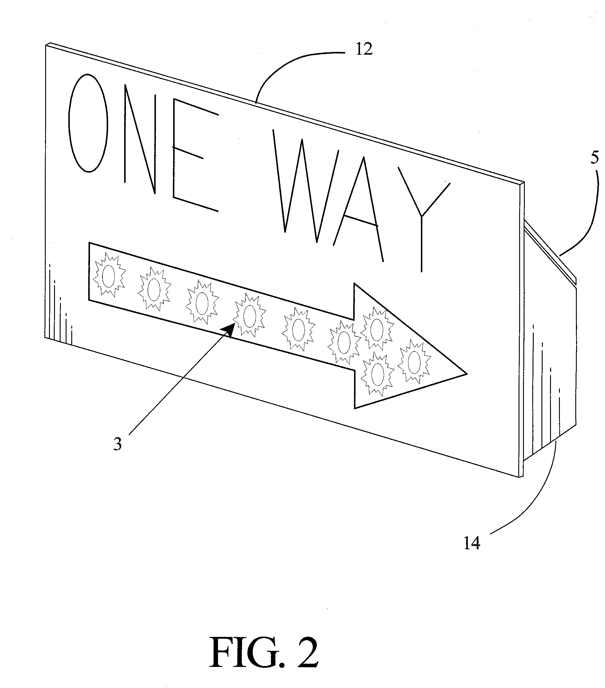
[0018] The present invention will be described using a one way sign as illustrative purposes only. To those knowledgeable in the art, other configurations are possible by arranging the various parts to provide annunciation to any other type traffic safety sign.

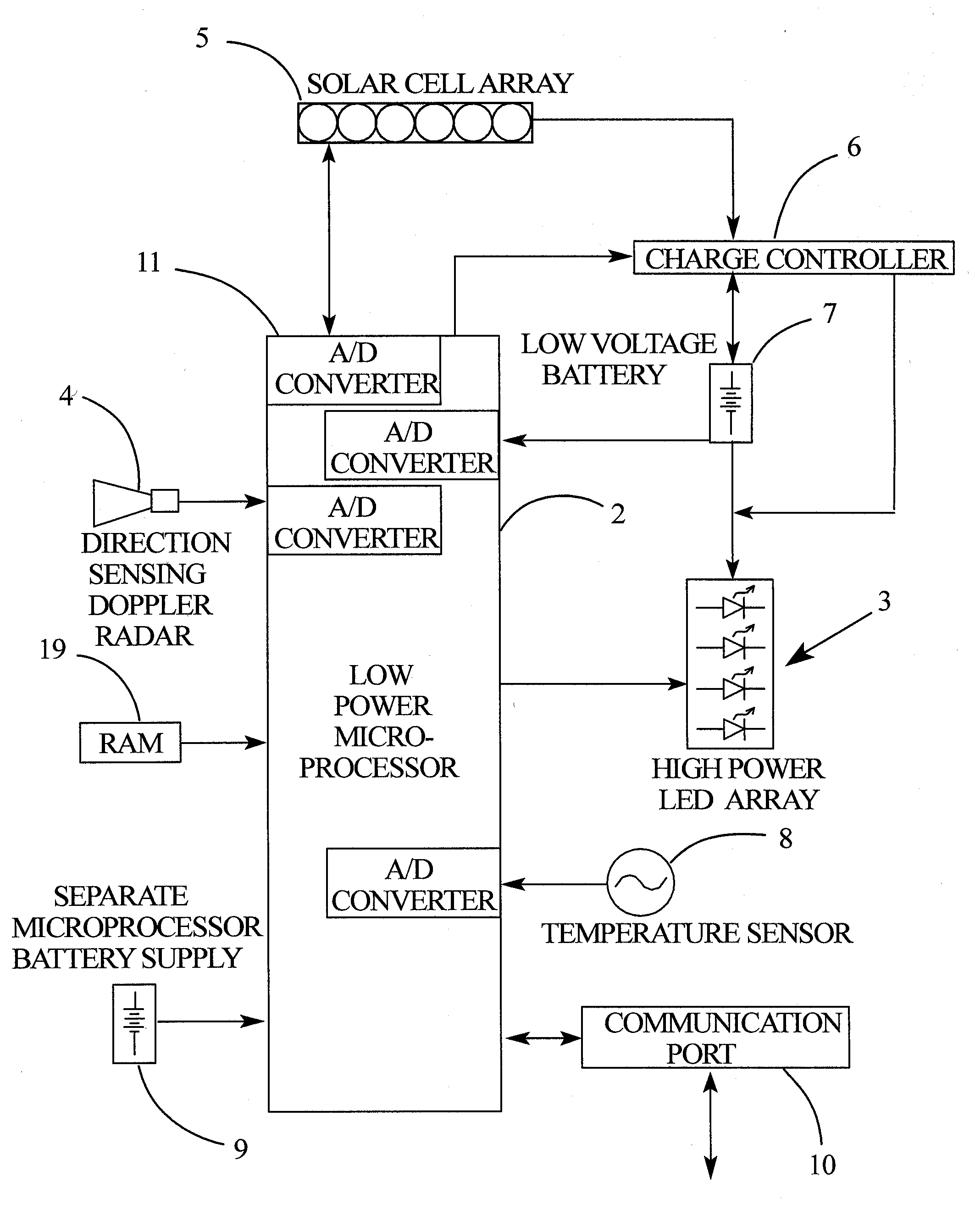
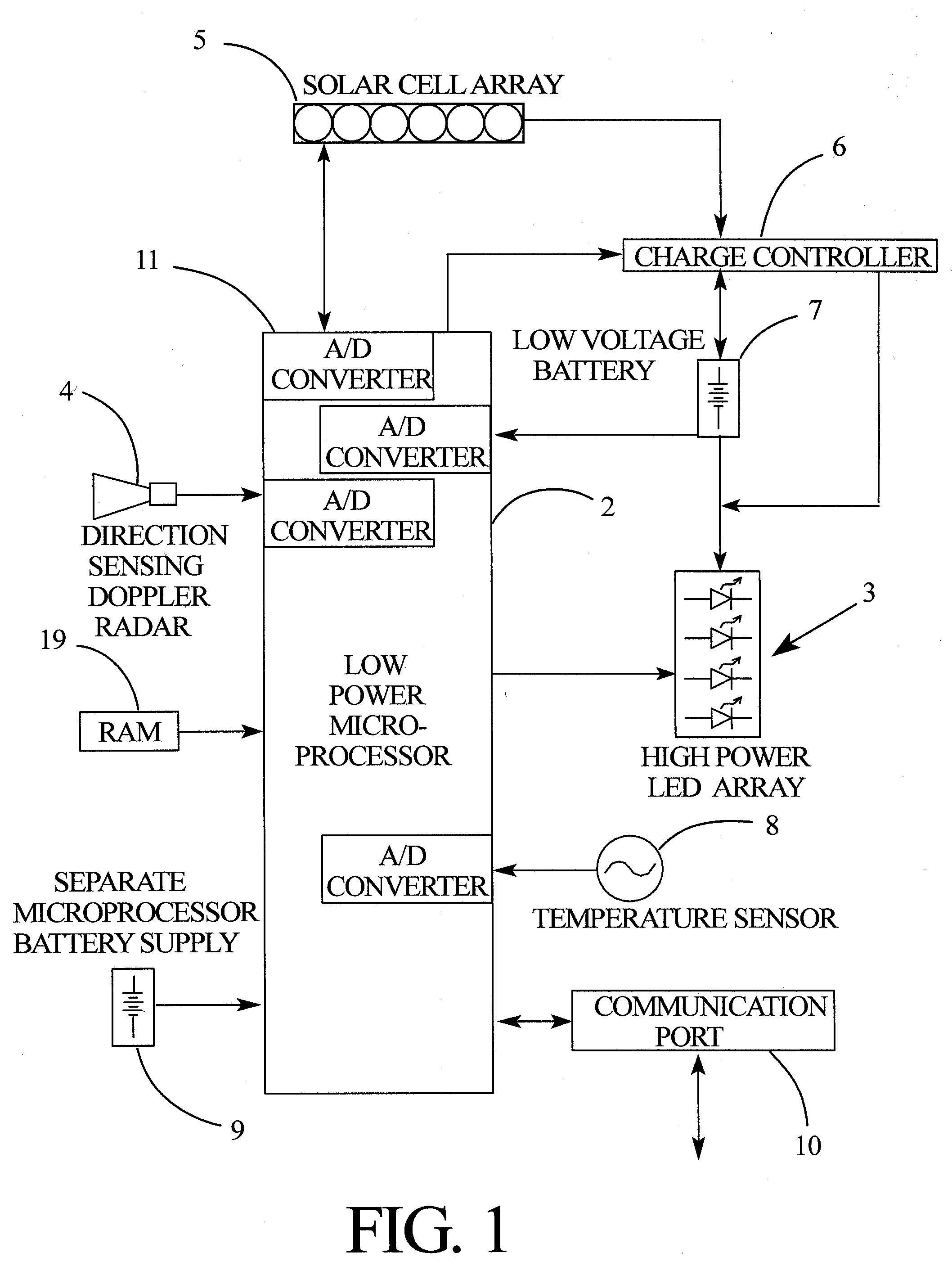
[0019] The elements of the present invention are illustrated in FIG. 1. The microprocessor controller 2 is an industry standard integrated circuit that is supplied in many different configurations consisting of varying plurality of input / output control lines, program and internal memory configurations and various other hardware options. It is not the intent of the present invention to specify the exact microprocessor configuration other to include a generic microprocessor as an integral feature of the invention necessary for the control of the subsystems. The microprocessor 2 contains a set of software routines burned into program memory that control and direct the internal operation of the microprocessor. The external random...


PUM


Abstract

A solar powered sign annunciator comprised of a plurality of high intensity light emitting diodes (LED); a microprocessor controller to regulate power consumption and annunciator characteristics, battery charging and sensor response with an integrated software charge controller; a minimalized solar panel array sized to produce sufficient power for battery charging under normalized solar radiation to latitudes as far north as 45 degrees; a direction sensing Doppler radar to determine the approach of traffic; a low voltage battery to minimize power control losses to the LED array; a temperature sensor to determine proper charging battery status and battery capacity; and a plurality of analog to digital (A / D) converters incorporated in the microprocessor to sense solar power output, temperature input, battery voltage and charging current and Doppler phase shift differential. The system also includes a housing arrangement to incorporate all aforementioned items in a weathertight enclosure providing sufficient horizontal surface for solar cell attachment yet in a package compact enough to easily attach to existing designed signs.

Description

BACKGROUND OF INVENTION [0001] Signs of all types are ubiquitous but in general we are asked to pay particular attention to signs that convey safety information. Many signs of this type are displayed virtually everywhere the general public travels. For example, lighted emergency exit signs shows us the way to an exit during fires while stop signs, way one signs, yield signs and many others guide us, caution us and inform us while driving. Everyone knows, for example, that a stop sign means to bring your vehicle to a stop and look for other traffic before proceeding. However, because of their common nature and ever-present appearance combined with other ordinary distractions that draw a driver's attention away from constant diligence, important safety signs are often missed, sometimes leading to catastrophic consequences. In recognition of this and in an attempt to draw a drivers attention to particularly important ones, attempts have been made to emphasis the more critical ones thro...

Claims


Application Information

Patent Timeline
Patent Type & Authority Applications(United States)
IPC IPC(8): G08G1/095
CPCG08G1/095
Inventor BLYTH, JOHN RANDOLPH
Owner BLYTH MR JOHN RANDOLPH
Learn More