Optical disk medium, optical disk medium production method, turntable and optical disk apparatus

a technology of optical disk and production method, applied in the direction of recording apparatus, instruments, record information storage, etc., can solve the problems production or manufacture efficiency is very low, and production cost is high, and achieve the effect of high density recording/reproduction

Inactive Publication Date: 2005-03-03
SONY CORP
View PDF0 Cites 1 Cited by
  • Summary
  • Abstract
  • Description
  • Claims
  • Application Information

AI Technical Summary

Benefits of technology

[0013] It is an object of the present invention to provide an optical disk medium, a turntable, and an optical disk apparatus wherein warping of the optical disk medium is eliminated to achieve high density recording / reproduction.
[0015] It is a further object of the present invention to provide an optical disk medium production method by which a plurality of optical disk media can be produced at a time to achieve a high production efficiency and reduction in production cost.
[0020] With the optical disk medium, turntable, and optical disk apparatus, since the optical disk medium includes a metal substrate made of a magnetic substance, when it is mounted on the disk receiving face of the turntable, it can be attracted to the disk receiving face by the magnetic force to correct any warping of the optical disk medium with a high degree of accuracy. Consequently, out-of-plane deflections of the optical disk medium upon rotation for recording and / or reproduction of data can be suppressed to a low level. Therefore, there is an advantage that a focusing error is not likely to occur and high density recording and / or reproduction can be anticipated.
[0024] With the optical disk medium, turntable and optical disk apparatus, the disk has no center hole, and a picture-character layer drawn or printed a picture, a character, or the like or a data recording layer can be formed in the wide area from the outer periphery to the portion within the radius of 0.5 mm to the center of the disk. Consequently, there is an advantage that an advertising effect and improvement in fine appearance by an increased area of the picture-character layer or implementation of a large capacity disk by an increased area of the data recording layer can be achieved.
[0027] With the optical disk medium production methods, since a plurality of small-size optical disk media can be produced at a time from a single large-size metal substrate, the production or manufacture efficiency of optical disk media is improved significantly and significant reduction of the production cost for optical disk media can be achieved.

Problems solved by technology

Any of such conventional optical disk media as described above is disadvantageous in that, when it is driven to rotate by a turntable to record and / or reproduce data on and / or from the optical disk medium by means of an optical pickup, if the optical disk medium has some warping, then out-of-plane deflections occur therewith upon rotation thereof and give rise to a focusing error or a tracking error.
Consequently, high density recording / reproduction cannot be anticipated.
Further, a region of a conventional optical disk medium in which a picture, a character or the like is displayed or a data recording region is limited to a small region of a portion of the optical disk medium between an outer side portion of a center hole and a data recording region.
Further, with the conventional optical disk medium production method described above, since a magnetic disk or the like is produced one by one, the production or manufacture efficiency is very low and a high production cost is required.
Further, where an optical disk medium has a center hole formed in a metal substrate, the region of a data recording region or a region in which a picture, a character or the like is to be displayed is restricted.

Method used


Image

  • Optical disk medium, optical disk medium production method, turntable and optical disk apparatus
  • Optical disk medium, optical disk medium production method, turntable and optical disk apparatus
  • Optical disk medium, optical disk medium production method, turntable and optical disk apparatus

Examples


embodiment 1

[0058] [Embodiment 1]

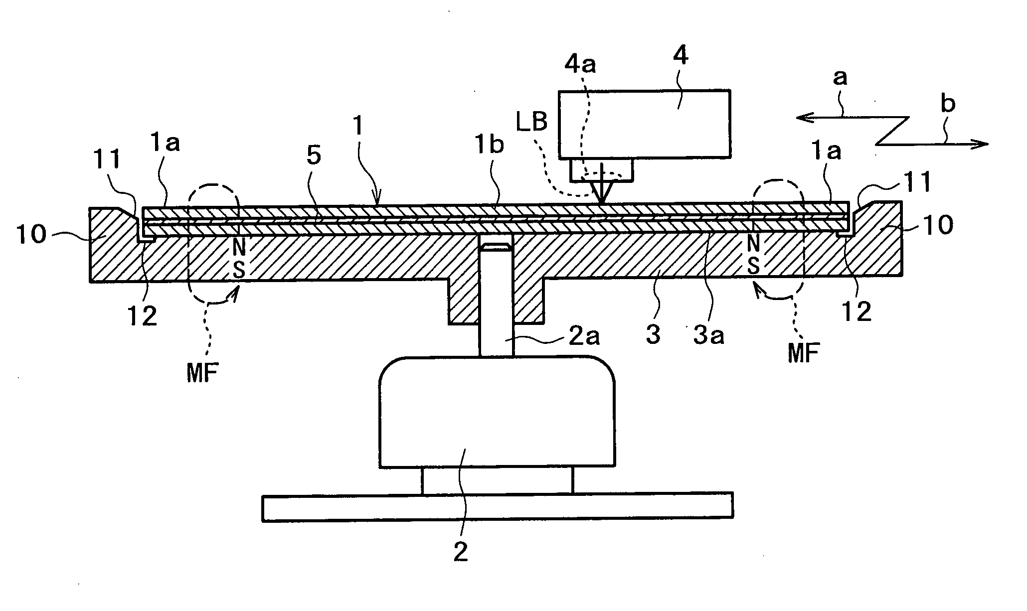
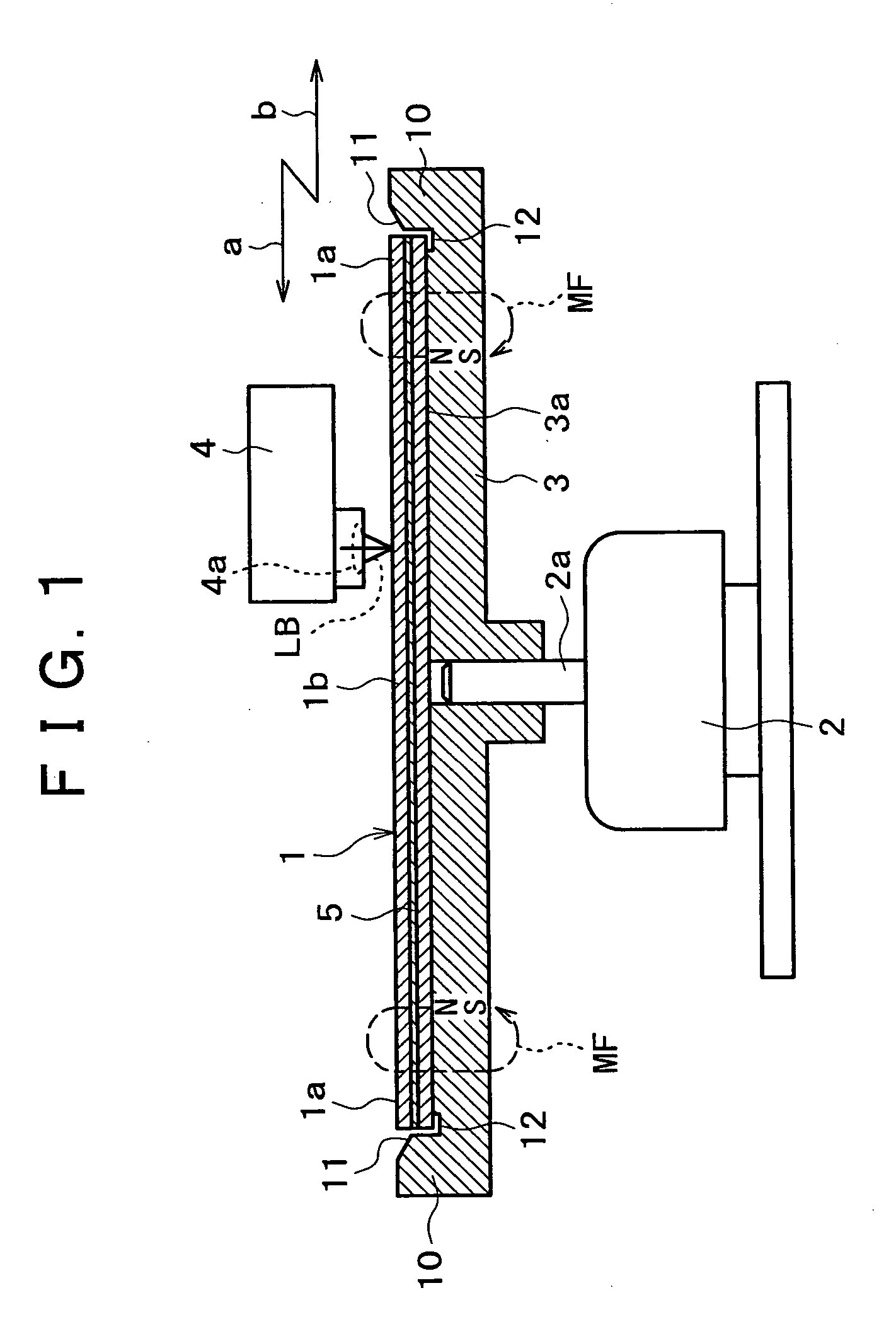
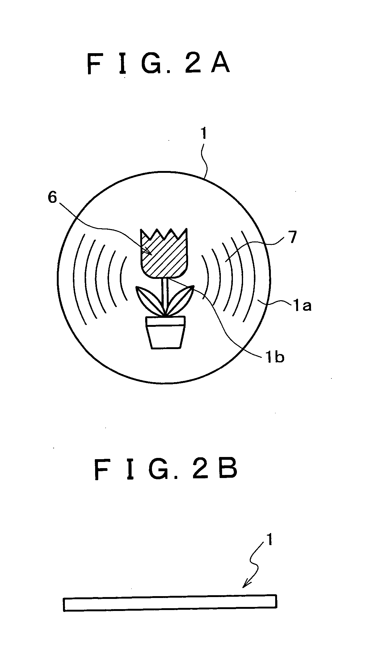
[0059] First, an outline of principal part of an optical disk apparatus of the present invention is described with reference to FIG. 1. An optical disk medium 1 of the present invention as represented by a compact disk (CD) and a digital versatile disk (DVD) is formed such that data is reproduced (read) therefrom using a light beam. However, the optical disk medium 1 may otherwise be formed such that data is magneto-optically recorded and / or reproduced (read) thereon and / or therefrom like a magneto-optical disk (MO). Although details of the optical disk medium 1 are hereinafter described, a metal substrate made of a magnetic substance is used as a disk substrate of the optical disk medium 1. It is to be noted that popular optical disk media use a disk substrate made of polycarbonate (PC).

[0060] A turntable 3 is secured by force fitting, adhesion, fastening by means of a screw or the like to an end of a motor shaft 2a of a spindle motor 2. While also details of ...

embodiment 2

[0090] [Embodiment 2]

[0091]FIG. 11 shows an embodiment 2 of the present invention. Referring to FIG. 11, a metal substrate 5 of an optical disk medium 1 is magnetized so that the optical disk medium 1 is attracted to a disk receiving face 3a of a turntable 3 formed from a magnetic substance such as an iron material by magnetic force MF of the metal substrate 5.

embodiment 3

[0092] [Embodiment 3]

[0093]FIG. 12 shows an embodiment 3 of the present invention. Referring to FIG. 12, a plurality of magnets 18 are embedded in a disk receiving face 3a of a turntable 3 so that the optical disk medium 1 is attracted to the disk receiving face 3a of the turntable 3 by magnetic force MF of the magnets 18. In this instance, the turntable 3 may be formed from a nonmagnetic material such as a plastics material.


PUM

PropertyMeasurementUnit
distanceaaaaaaaaaa
radiusaaaaaaaaaa
diameteraaaaaaaaaa

Abstract

An optical disk that is prevented from being warped when it is driven to rotate by a turntable includes a disk substrate formed as a metal substrate made of a magnetic substance. When the optical disk is mounted on a disk receiving face of the turntable, the metal substrate is attracted to the disk receiving face of the turntable by the magnetic force, thereby to correct any warping of the optical disk medium with a high degree of accuracy.

Description

BACKGROUND OF THE INVENTION [0001] This invention relates to an optical disk medium on and / or from which data is recorded and / or reproduced by an optical system or a magneto-optical system, a turntable for driving the optical disk to rotate, and an optical disk apparatus wherein data is recorded on and / or reproduced from the optical disk medium by means of an optical pickup while the turntable is driven by a spindle motor to rotate the optical disk medium. [0002] The present invention relates also to a method of producing an optical disk on and / or from which data is recorded and / or reproduced by an optical system or a magneto-optical system. [0003] An optical disk medium such as an optical disk or a magneto-optical disk on and / or from which data is recorded and / or reproduced by an optical system or a magneto-optical system includes a data recording layer of optical pits, a magnetic film or the like formed on one or both of the opposite faces of a disk substrate and a transparent pro...

Claims


Application Information

Patent Timeline
Patent Type & Authority Applications(United States)
IPC IPC(8): G11B7/258G11B17/028G11B19/20G11B23/00G11B23/40
CPCG11B7/2532G11B7/258G11B17/028G11B23/40G11B19/2009G11B23/0021G11B17/0282
Inventor KANAZAWA, TAKAKIYOMIURA, TAKAHIROWATANABE, HIDETOSHI
Owner SONY CORP
Why Eureka
Try Eureka