
Method of fabricating ultra-fine cermet alloys with homogeous solid grain structure

Inactive Publication Date: 2005-03-03
KOREA INST OF SCI & TECH
View PDF7 Cites 26 Cited by
  • Summary
  • Abstract
  • Description
  • Claims
  • Application Information

AI Technical Summary

Benefits of technology

Another object of the present invention is to provide a high hardness TiC-base cermet alloy with ultra-fine grains which has a uniform microstructure in the alloy.
The above objects of the present invention could be achi

Problems solved by technology

This also has some drawbacks of deteriorating the physical property of the sintering body.
To date, however, no fabrication method of TiC-base cermet alloys with the core-rim structure were able to overcome the limit of kinectic determination.
However, the gas phase or solid state reaction method is inappropriate for massive manufacturing of carbide nano-powders, because the carbide nano-powders obtained from such methods could easily be oxidized when exposed to the atmosphere.

Method used


Image

  • Method of fabricating ultra-fine cermet alloys with homogeous solid grain structure
  • Method of fabricating ultra-fine cermet alloys with homogeous solid grain structure
  • Method of fabricating ultra-fine cermet alloys with homogeous solid grain structure

Examples


embodiment 1

[Preferred Embodiment 1]

Ti powder with a purity value above 99.7% and diameter less than 45 μm, Mo powder with a purity value above 99.7% and diameter less than 5 μm, C powder with a purity value above 99% and diameter less than 5 μm, Ni powder with a purity value above 99.7% and diameter less than 6 μm are mixed to form powder mixture of TiC 60 wt %, Mo2C 20 wt % and Ni 20 wt %.

The powder mixture is put into a tool steel milling jar together with tool steel balls with diameter of 9.5 mm where the weight ratio between the powder mixture and balls is 10:1. Next, high energy ball milling is carried out for 20 hours after the milling jar is charged with argon gas.

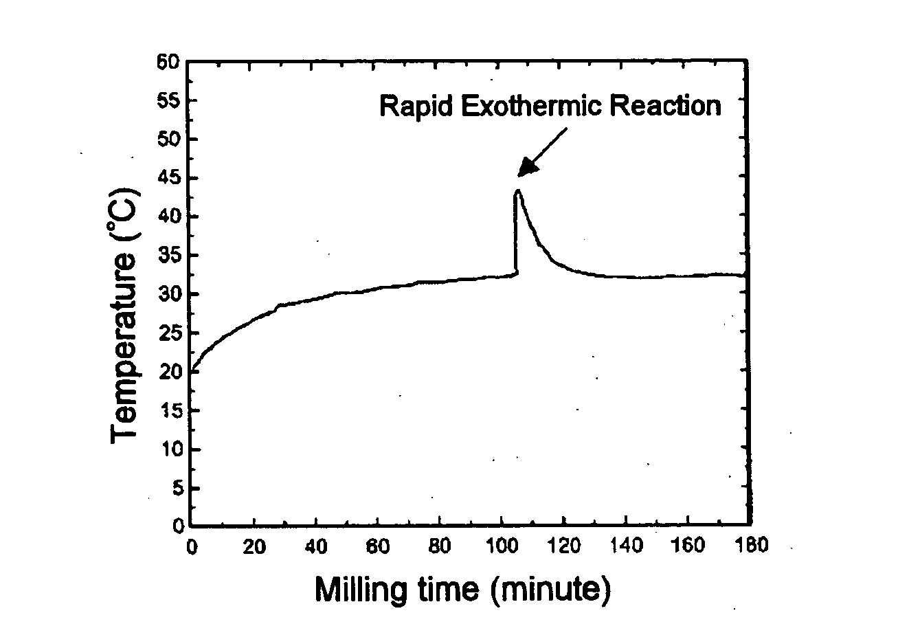
The surface temperature of the milling jar is measured using a non-contact type infrared thermometer.

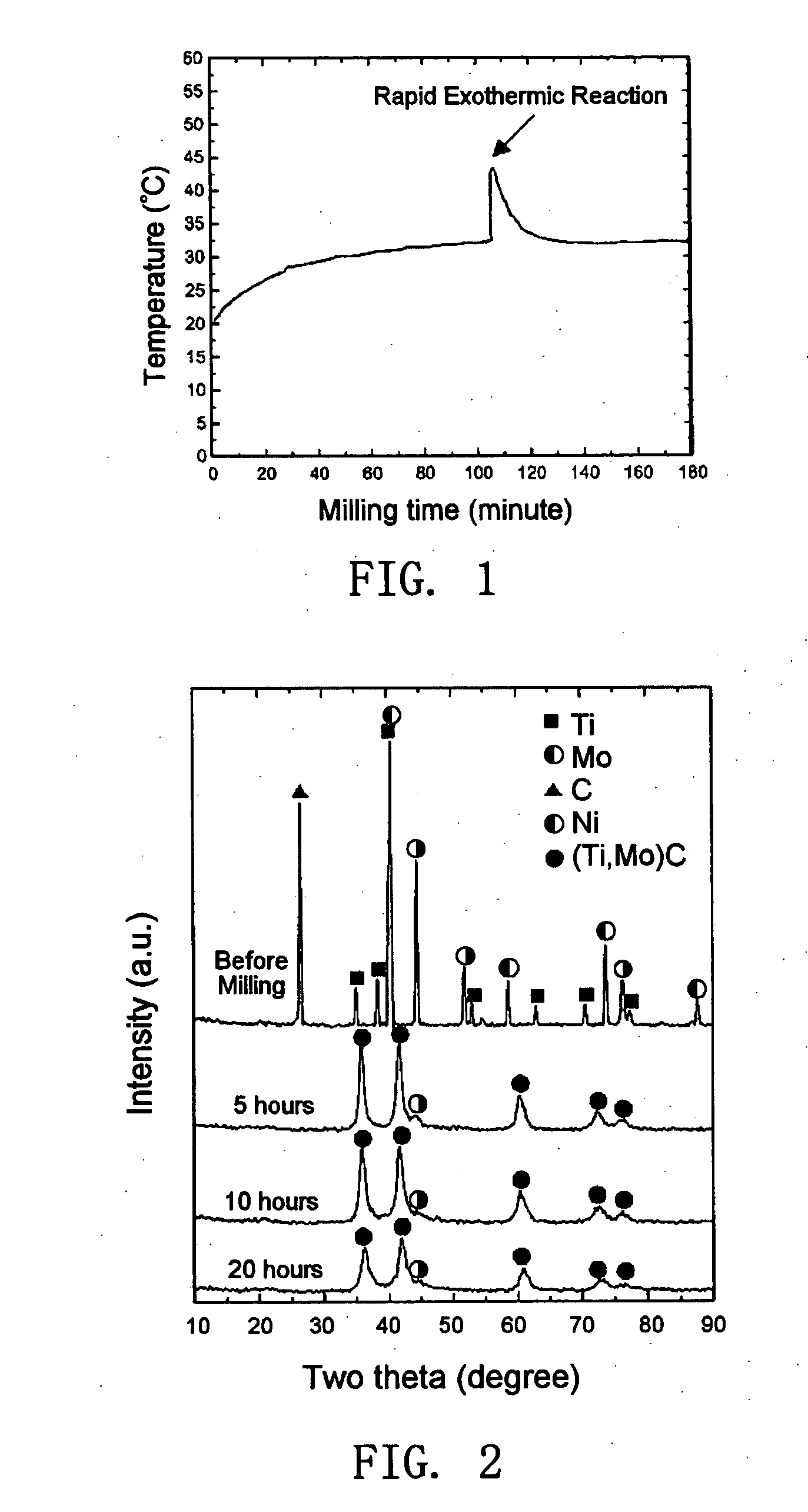
As shown in FIG. 1, a sharp temperature rise on the surface of the milling jar is found in 100 minutes during milling.

The milled composite powders dried, granulated and compacted under a pressure of 20 MPa. The compact...

embodiment 2

[Preferred Embodiment 2]

Ti powder with a purity value above 99.7% and aiameter less than 45 μm, W powder with a purity value above 99% and diameter less than 1 μm, C powder with a purity value above 99% and diameter less than 5 μm, Ni powder with a purity value above 99.8% and diameter less than 6 μm, Co powder with diameter less than 10 μm are mixed to form a powder mixture of TiC 65 wt %, WC 20 wt %, Ni 8 wt % and Co 7 wt %.

The powder mixture is put into a tool steel milling jar together with tool steel balls with a diameter of 8 mm where the weight ratio between the powder mixture and balls is 23:1. Next, high energy ball milling is carried out for 5 hours using a planetary mill after the milling jar is charged with argon gas.

The surface temperature of the milling jar is measured using a non-contact type infrared thermometer.

The milled composite powder is dried, granulated and compacted under a pressure of 20 MPa. The compact is sintered under a 10−5 torr vacuum condition ...


PUM

PropertyMeasurementUnit
Temperatureaaaaaaaaaa
Fractionaaaaaaaaaa

Abstract

The present invention relates to a method of fabricating ultra-fine grain cermet alloys with a homogenous solid solution grain structure. More particularly, the invention relates to a method of fabricating an ultra-fine TiC-base cermet alloy with a homogenous solid solution structure which does not comprise a core-rim structure in the carbide grain. The object of the present invention is to provide a method of fabricating a TiC-base cermet alloy without the core-rim structure. The above objects of the present invention could be achieved by employing a conventional sintering process (vacuum sintering) of (Ti,TM)C carbide obtained from a mechano-chemical synthesis (high energy ball-milling) from milling the powders of Ti, TM, Ni and Co metals.

Description

BACKGROUND OF THE INVENTION The present invention relates to a method of fabricating ultra-fine cermet alloys with a homogenous solid solution grain structure. More particularly, the invention relates to a method of fabricating an ultra-fine TiC-base cermet alloy with a homogenous solid solution grain structure that does not comprise a core-rim structure in the carbide grain. In general, the ultra-fine TiC-base cermet alloys are used as cutting tools for the finishing works of steel and cast iron due to their high hardness and abrasion resistance characteristics. The sintered body of a TiC-base cermet alloy comprises a distinctive dual structure in its carbide grains. This dual structure which is known as the core-rim structure comprises a center region (core) in which the main component includes TiC or TiCN, and a outer (peripheral) second region (rim) which surrounds the core and is mainly a carbide of solid solution such as (Ti, TM)C or (Ti, TM) (C, N), (See, FIG. 8: In refere...

Claims


Application Information

Patent Timeline
IPC IPC(8): B22F1/00B22F7/00B22F3/14C22C1/10C22C29/06C22C29/10
CPCC22C1/1084B22F1/0044C22C29/06B22F1/07C22C29/10B82Y40/00
Inventor SHIM, JAE HYEOKPARK, JONG KUCHO, YOUNG WHAN
Owner KOREA INST OF SCI & TECH
Learn More