Multiple stage combustion process to maintain a controllable reformation temperature profile

a technology of reformation temperature and combustion process, applied in the field of fuel cell systems and components, can solve the problems of endothermic reformation process, inapplicability, and limited fuel cell development, and achieve the effect of more uniform and/or controllable heat generation and exchange, uniform and/or controllable temperature profile, and added to the overall mass and volume of the fuel cell system

Inactive Publication Date: 2005-03-03
GM GLOBAL TECH OPERATIONS LLC
View PDF17 Cites 26 Cited by
  • Summary
  • Abstract
  • Description
  • Claims
  • Application Information

AI Technical Summary

Benefits of technology

[0019] The invention includes a reaction vessel that integrates and balances an endothermic process with at least one exothermic process of a fuel cell system. Preferably the exothermic process is conducted in stages to provide more uniform and / or controllable heat generation and exchange, and to produce a uniform, and / or controllable temperature profile in the endothermic reaction process, if desired (depending on the fuel used). The invention eliminates the working fluid heat exchange loop of prior art fuel reforming sections that had unsatisfactory response times at startup, and during transient conditions, and also added to the overall mass and volume of the fuel cell system.

Problems solved by technology

Since then most of the fuel cell development has been primarily limited to applications supported by the government, such as the United States National Aeronautics and Space Administration (NASA), or to utility plants applications.
Although compressed or liquefied hydrogen could be used to operate a fuel cell in a vehicle, to date this is not practical.
However, these reforming (reformation) processes are endothermic and require energy input to drive the reformation reaction.
However, the response time for heat transfer needed during startup and transient conditions of the fuel cell are less than optimal when the system uses a fluid to transfer heat between the combustor and the reformer vessel.
Further, the working fluid loop, associated heat exchangers and piping add to the overall mass and volume of the fuel cell system.

Method used


Image

  • Multiple stage combustion process to maintain a controllable reformation temperature profile
  • Multiple stage combustion process to maintain a controllable reformation temperature profile
  • Multiple stage combustion process to maintain a controllable reformation temperature profile

Examples


Embodiment Construction

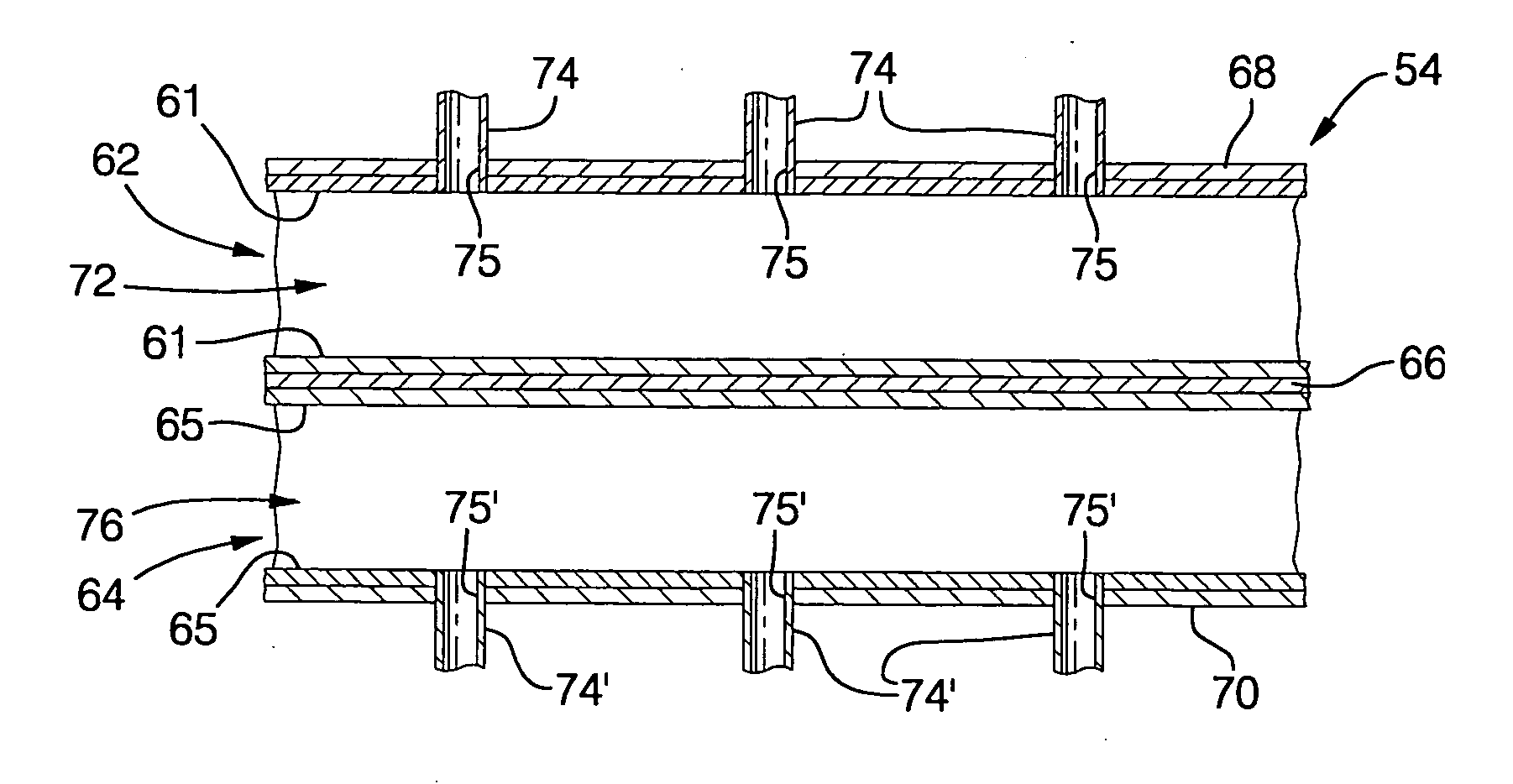
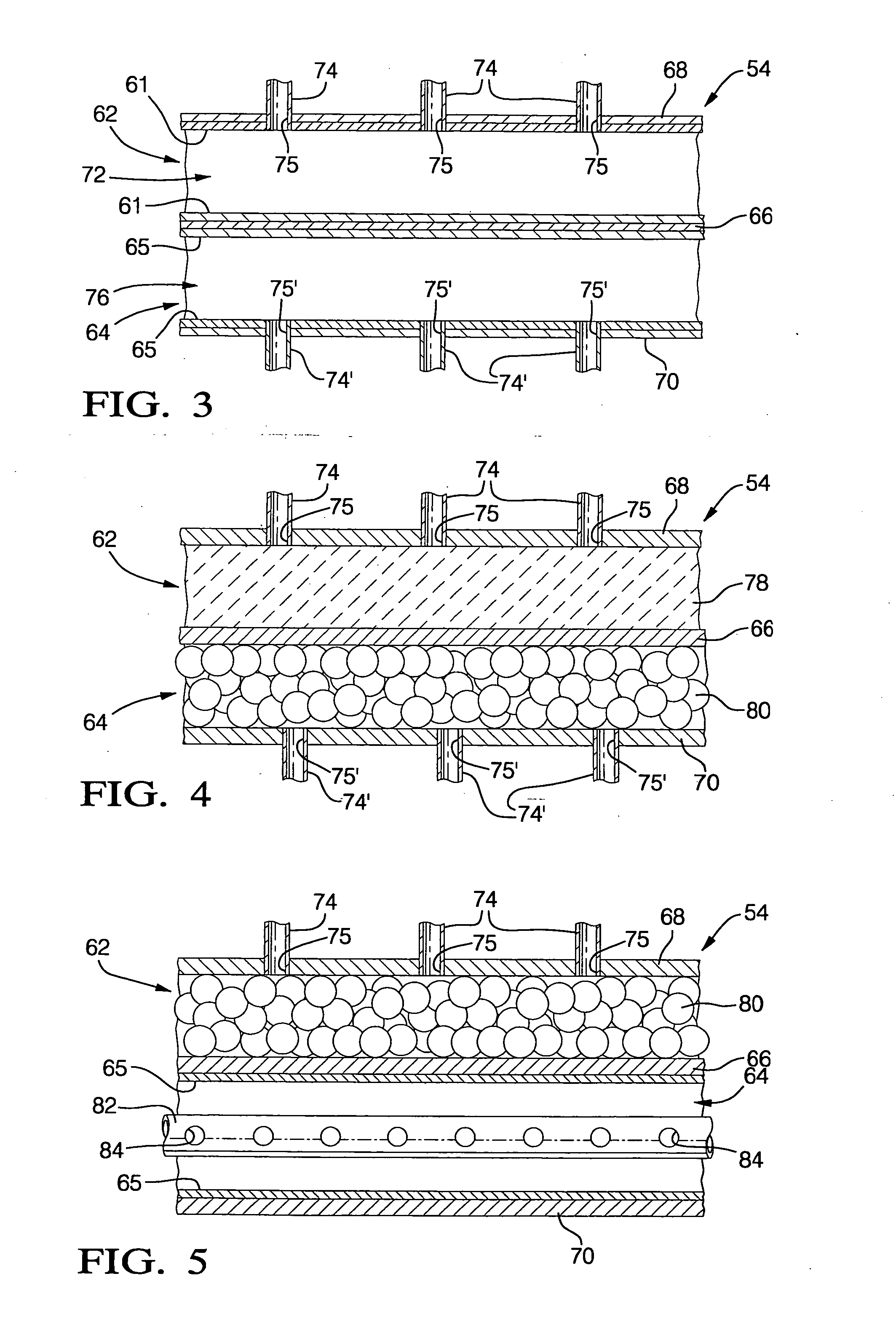
[0034] Referring now to FIG. 2, the fuel cell system according to the present invention includes a fuel cell (or fuel cell stack) 10. The system may also include the following auxiliary equipment to support the fuel cell stack 10. Water is provided and held in a water reservoir or holding tank 46 which is connected to a vaporizer 48 by water line 44. A fuel source is provided and held in a tank 52 that is also connected to the vaporizer 48 by line 50. Preferably the fuel used is methanol, gasoline, diesel, methane and the like. The fuel and water may be vaporized by any method known to those skilled in the art, but preferably the heat for the vaporization step is supplied by a heat exchanger 39 in the vaporizer that catalytically combusts hydrogen 40′ and oxygen 42′ from the fuel cell stack 10 exhaust. Alternatively, the vaporizer may be included as an integral part of the reaction vessel 54 as will be described hereafter. The fuel and water are vaporized together (or may be vaporiz...


PUM

PropertyMeasurementUnit
pressureaaaaaaaaaa
temperatureaaaaaaaaaa

Abstract

A reaction vessel that integrates and balances an endothermic process with at least one exothermic process of the fuel cell system. Preferably the exothermic process is conducted in stages to provide more uniform and / or controllable heat generation and exchange, and to produce a uniform and / or controllable temperature profile in the endothermic reaction process. The invention allows for the elimination of the working fluid loop of prior art systems that had unsatisfactory response times at startup, and during transient conditions, and also added to the overall mass and volume of the fuel cell system.

Description

TECHNICAL FIELD [0001] This invention relates to fuel cell systems and components, and more particularly to a fuel cell system that combines exothermic and endothermic processes in one reaction vessel. BACKGROUND OF THE INVENTION [0002] Alexander Grove invented the first fuel cell in 1839. Since then most of the fuel cell development has been primarily limited to applications supported by the government, such as the United States National Aeronautics and Space Administration (NASA), or to utility plants applications. However, recent developments in materials of construction and processing techniques have brought fuel cell development closer to significant commercial applications. A primary advantage of fuel cells is that fuel cells can convert stored energy to electricity with about 60-70 percent efficiency, with higher efficiencies theoretically possible. Further, fuel cells produce virtually no pollution. These advantages make fuel cells particularly suitable for vehicle propulsio...

Claims


Application Information

Patent Timeline
Patent Type & Authority Applications(United States)
IPC IPC(8): F23K5/00B01J19/24C01B3/32C01B3/38C01B3/58F23G7/06F23G7/07H01M8/04H01M8/06
CPCB01J19/249Y02E60/50B01J2219/2458B01J2219/2464B01J2219/2465B01J2219/247B01J2219/2479B01J2219/2481B01J2219/2485B01J2219/2487B01J2219/2496C01B3/384C01B3/583C01B2203/00C01B2203/0233C01B2203/044C01B2203/047C01B2203/066C01B2203/0811C01B2203/0822C01B2203/0827C01B2203/1029C01B2203/1223C01B2203/1235C01B2203/1288C01B2203/1619C01B2203/1676C01B2203/1695H01M8/04022H01M8/04223H01M8/0612B01J2219/2453H01M8/241H01M8/04225H01M8/2457H01M8/2484Y02P20/10H01M8/0258
Inventor PETTIT, WILLIAM HENRY
Owner GM GLOBAL TECH OPERATIONS LLC
Why Eureka
Try Eureka