Dry aerosol leak detection for dialyzers

a dialyzer and aerosol technology, applied in the field of medical devices, can solve problems such as leakage, and achieve the effects of minimizing particle loss, high flow rate, and fast response tim

Inactive Publication Date: 2005-03-10
BAXTER INT INC
View PDF65 Cites 14 Cited by
  • Summary
  • Abstract
  • Description
  • Claims
  • Application Information

AI Technical Summary

Benefits of technology

[0016] It is therefore an advantage of the present invention to provide a dialyzer leak test having a fast response time.
[0017] It is another advantage of the present invention to provide a dialyzer leak test that points to a source or location of a leak.
[0018] It is a further advantage of the present invention to provide a dialyzer leak test that uses a polydisperse aerosol to minimize particle loss.
[0019] Further still, it is an advantage of the present invention to use multiple pressure and particle concentration reducing steps in the test aerosol flow path to adjust the aerosol to the size of leak that needs to be detected.
[0020] It is still another advantage of the present invention to provide a dialyzer leak test that uses a relatively high flowrate to reduce particle loss and increase particle detection.
[0021] Moreover, it is an advantage of the present invention to provide a dialyzer leak test having several testing paths on one unit to reduce particle losses and increase the probability of detecting fiber or potted end defects at low leak rates.

Problems solved by technology

With dialyzers, leakage occurs when one or more openings appears in the hollow fiber walls or potted ends that allow red blood cell to pass from the dialyzer fibers.

Method used


Image

  • Dry aerosol leak detection for dialyzers
  • Dry aerosol leak detection for dialyzers
  • Dry aerosol leak detection for dialyzers

Examples


Embodiment Construction

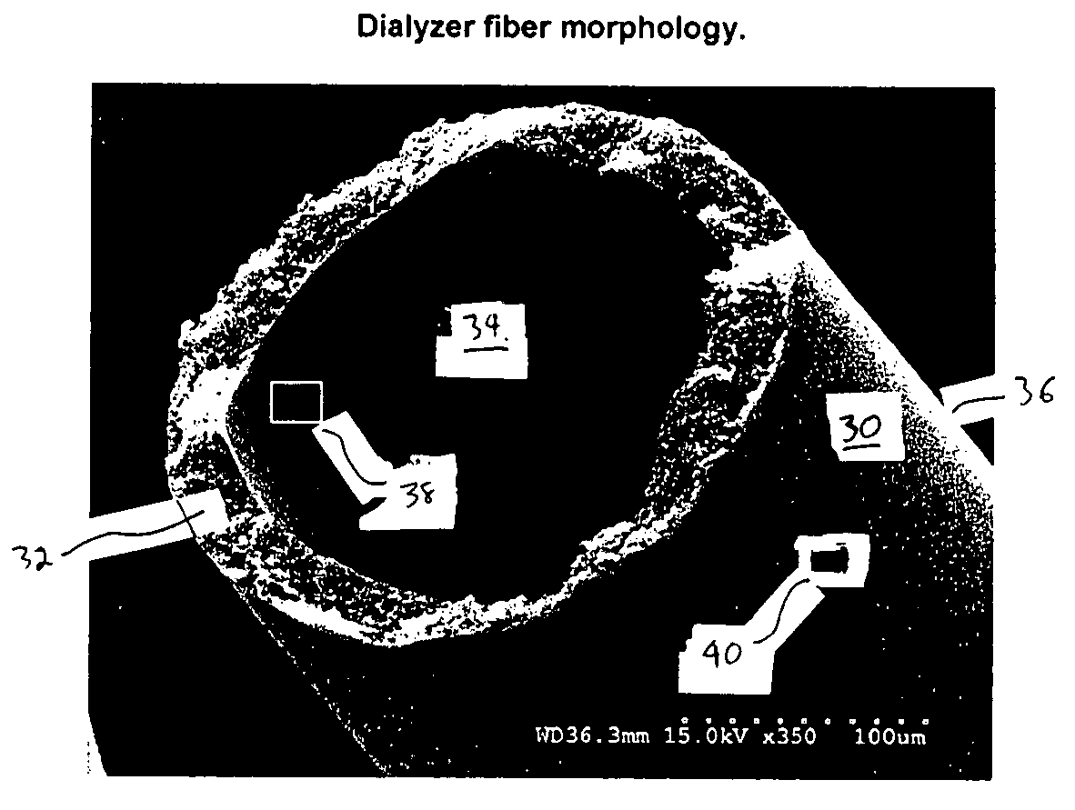
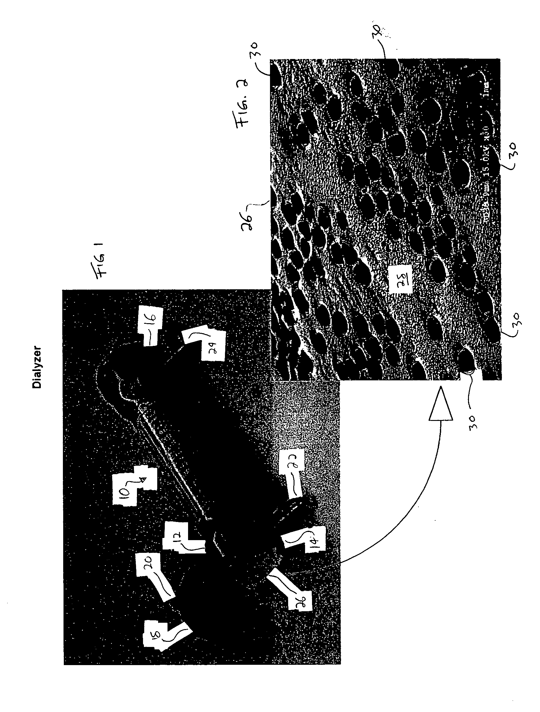
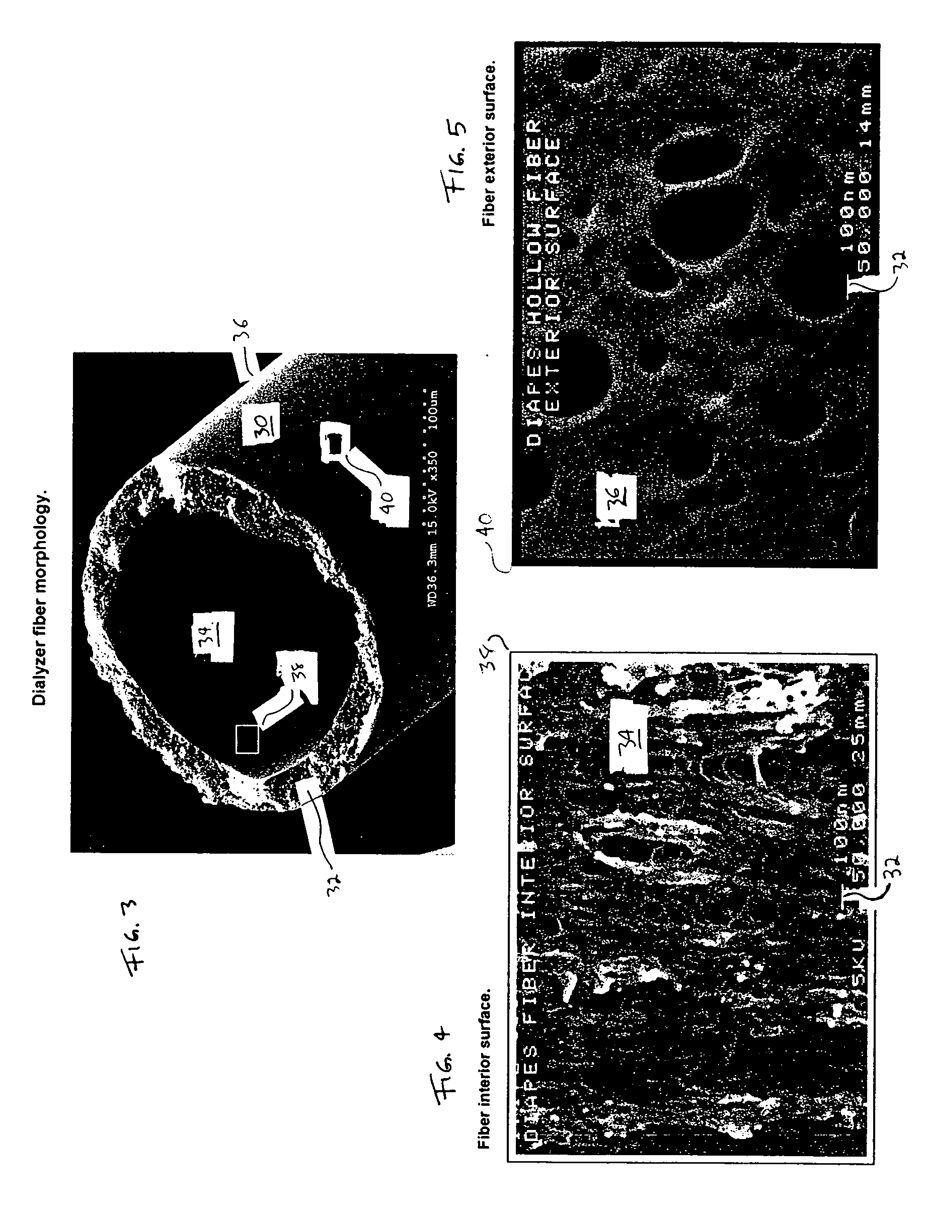
[0033] The present invention provides a system and method for testing the integrity of hollow fibers placed inside of a device. The device is any type of device used for filtering or cleaning that employs hollow, multi-porous fibers, such as devices for the filtration of aqueous and gaseous fluids, ultrafiltration of particles and the dialysis of blood. Although the present invention will be described in connection with a dialyzer for blood dialysis, it is expressly contemplated that the system and method described herein can be used with equal effectiveness in these other applications.

[0034] Referring now to the figures and in particular to FIGS. 1 and 2, a dialyzer 10 is illustrated. Dialyzer 10 includes a clear or translucent plastic housing 12. Housing 12 defines open ends 14 and 16. As described in more detail below, each of the ends 14 and 16 is potted with a polymer or resin material that seals the interstices between the fibers and the space between the outside of the hollo...


PUM

PropertyMeasurementUnit
sizeaaaaaaaaaa
sizeaaaaaaaaaa
diameteraaaaaaaaaa

Abstract

The present invention provides a leak testing method and system therefore for any type of filtering device employing hollow fibers, such as filtration of aqueous or gaseous fluids, ultrafiltration of particulate materials and dialysis of blood. In an embodiment, the leak test is employed in testing a bundle of fibers placed in a dialyzer. The dialyzer includes a blood inlet and a blood outlet, wherein blood flows through the inside of a plurality of hollow fibers. Dialysate flows into the dialyzer through an inlet port, around the outside of the hollow fibers and out of the dialyzer through an outlet port. The test employs a dry aerosol that is injected into the blood inlet, outlet or both, wherein a particle counter counts particles that pass through the fiber walls and exit one or both the dialysate ports. If the counter detects more than an acceptable amount of particles, the dialyzer has a leak.

Description

BACKGROUND OF THE INVENTION [0001] This invention relates generally to the field of medical devices. More particularly the present invention relates to a method for testing medical devices. [0002] It is known to provide dialysis to treat kidney failure. To this end, different methods of providing dialysis have been developed. One type of dialysis is hemodialysis, which removes waste from a patient's blood. Hemodialysis is performed using machines that include typically an extracorporeal blood circuit. The blood circuit includes an arterial line, a blood pump, a dialyzer and a venous line. The patient is connected to the arterial and venous lines via a catheter inserted into the patient's vein or artery. The blood pump removes blood from the patient and pumps same through the arterial line to an inlet or blood side of the membrane in the dialyzer. The dialyzer includes typically a semipermeable membrane that separates waste components, such as proteins, toxins and excess water from t...

Claims


Application Information

Patent Timeline
Patent Type & Authority Applications(United States)
IPC IPC(8): A61M1/16B01D63/02B01D65/10G01N1/22G01N1/34G01N15/06
CPCA61M1/16A61M2205/705A61M2209/02G01N2001/4066B01D65/104G01N1/2205G01N15/065B01D63/02A61M2205/3334A61M2205/50
Inventor BARBER, TOMLENART, JIMZUPEC, NEAL
Owner BAXTER INT INC
Why Eureka
Try Eureka