
Machining power supply for wire electrical discharge machine

a technology of wire electrical discharge and power supply, which is applied in the direction of metal-working equipment, manufacturing tools, electrical-based machining equipment, etc., can solve the problems of easy over-extension of the breakage limit of the wire electrode, inability to perform fine energy control, and inability to control the pulse waveform of the electric current, so as to improve the speed of machining and ensure safe operation. , the effect of wire electrod

Inactive Publication Date: 2005-03-10
MITSUBISHI ELECTRIC CORP
View PDF8 Cites 7 Cited by
  • Summary
  • Abstract
  • Description
  • Claims
  • Application Information

AI Technical Summary

Benefits of technology

The present invention is directed at solving these problems and has as an object the realization of a machining electrical power supply device for a wire electrical discharge machining apparatus, in which, even in the field of high-speed machining, wire electrode breakage can be avoided and machining speed can be improved.
Further, the machining electrical power supply device for the wire electrical discharge machining apparatus related to this invention is provided with: a trapezoidal wave output counting means for counting the trapezoidal wave output count (Ntz) only, and an all-waveforms output counting means for counting all the trapezoidal wave and triangular wave output counts (Nto), wherein, in cases where the ratio (Ntz / Nto) is large, the inter-electrode current waveform control means increases the pulse width of the trapezoidal wave current supplied to the electrodes, and, in cases where the ratio (Ntz / Nto) is small, the inter-electrode current waveform control means decreases the pulse width of the trapezoidal wave current supplied to the electrodes.
Further, the machining electrical power supply device for the wire electrical discharge machining apparatus related to this invention is provided with: a triangular wave output counting means for counting the triangular wave output count (Nta) only, and an all-waveforms output counting means for counting all the trapezoidal wave and triangular wave output counts (Nto), wherein, in cases where the ratio (Nta / Nto) is small, the inter-electrode current waveform control means increases the pulse width of the trapezoidal wave current supplied to the electrodes, and, in cases where the ratio (Nta / Nto) is large, the inter-electrode current waveform control means decreases the pulse width of the trapezoidal wave current supplied to the electrodes.
Further, the machining electrical power supply device for a wire electrical discharge machining apparatus related to this invention is provided with: a trapezoidal wave output counting means for counting the trapezoidal wave output count (Ntz) only, and an all-waveforms output counting means for counting all the trapezoidal wave and triangular wave output counts (Nto), wherein, in cases where the ratio (Ntz / Nto) is large, the inter-electrode current waveform control means increases the peak value of the trapezoidal wave current supplied to the electrodes, and, in cases where the ratio (Ntz / Nto) is small, the inter-electrode current waveform control means decreases the peak value of the trapezoidal wave current supplied to the electrodes.
Further, the machining electrical power supply device for a wire electrical discharge machining apparatus related to this invention is provided with: a triangular wave output counting means for counting the triangular wave output count (Nta) only, and an all-waveforms output counting means for counting all the trapezoidal wave and triangular wave output counts (Nto), wherein, in cases where the ratio (Nta / Nto) is small, the inter-electrode current waveform control means increases the peak value of the trapezoidal wave current supplied to the electrodes, and, in cases where the ratio (Nta / Nto) is large, the inter-electrode current waveform control means decreases the peak value of the trapezoidal wave current supplied to the electrodes.
The machining electrical power supply device for a wire electrical discharge machining apparatus related to this invention, configured as above, has advantages in that wire electrode breakage can be avoided even in the high-speed machining field, and machining can be safely carried out. A further advantage is that machining speed can be improved.

Problems solved by technology

With the machining electrical power supply device in this conventional wire electrical discharge machine, electrical current pulse peak values are set for each of normal, abnormal, and electrical shorting states, but the electrical current pulse waveform cannot be controlled according to the result of the distinguishing circuit.
With the machining electrical power supply device in the conventional wire electrical discharge machine, even in the high-speed machining field, in which machining gaps are narrow, an energy change in the current pulse flowing to the electrodes in order to eliminate the electrical shorting merely controls changes in the peak values, as described above, and cannot perform fine energy control.
When machining speed is increased in the high-speed machining field close to the breaking limit of the wire electrode, the controllable area for avoiding the breakage of the wire electrode becomes narrow, and thus the breakage limit of the wire electrode is easily exceeded, and since it is difficult to safely avoid the electrode wire breakage, ultimately there has been a problem in that the machining speed cannot be increased.
Further, in order to perform high-speed machining, the electrical load per current pulse must be made large in order to make the electrical discharge energy large; however, the higher the peak value of the inter-electrode current the more easily the wire electrode is broken, and with the conventional inter-electrode current waveform as in FIG. 14, in order to make the electrical discharge energy large, the area of the inter-electrode current waveform is made large, and the only way to do this is to raise the peak value; thus, there has been a problem in that it is not possible to improve the machining speed while inhibiting the breakage of the wire electrode.
In addition, because the frequency of electrical shorting increases in the high-speed machining field, the current pulse, which flows to the electrodes in order to eliminate electrical shorting, contributes to bridge elimination in electrical shorting members but not directly to the electrical discharge itself, and thus, in the high-speed machining field, there has been a problem in that electrical power that does not directly contribute to the machining increases.

Method used


Image

  • Machining power supply for wire electrical discharge machine
  • Machining power supply for wire electrical discharge machine
  • Machining power supply for wire electrical discharge machine

Examples


embodiment 1

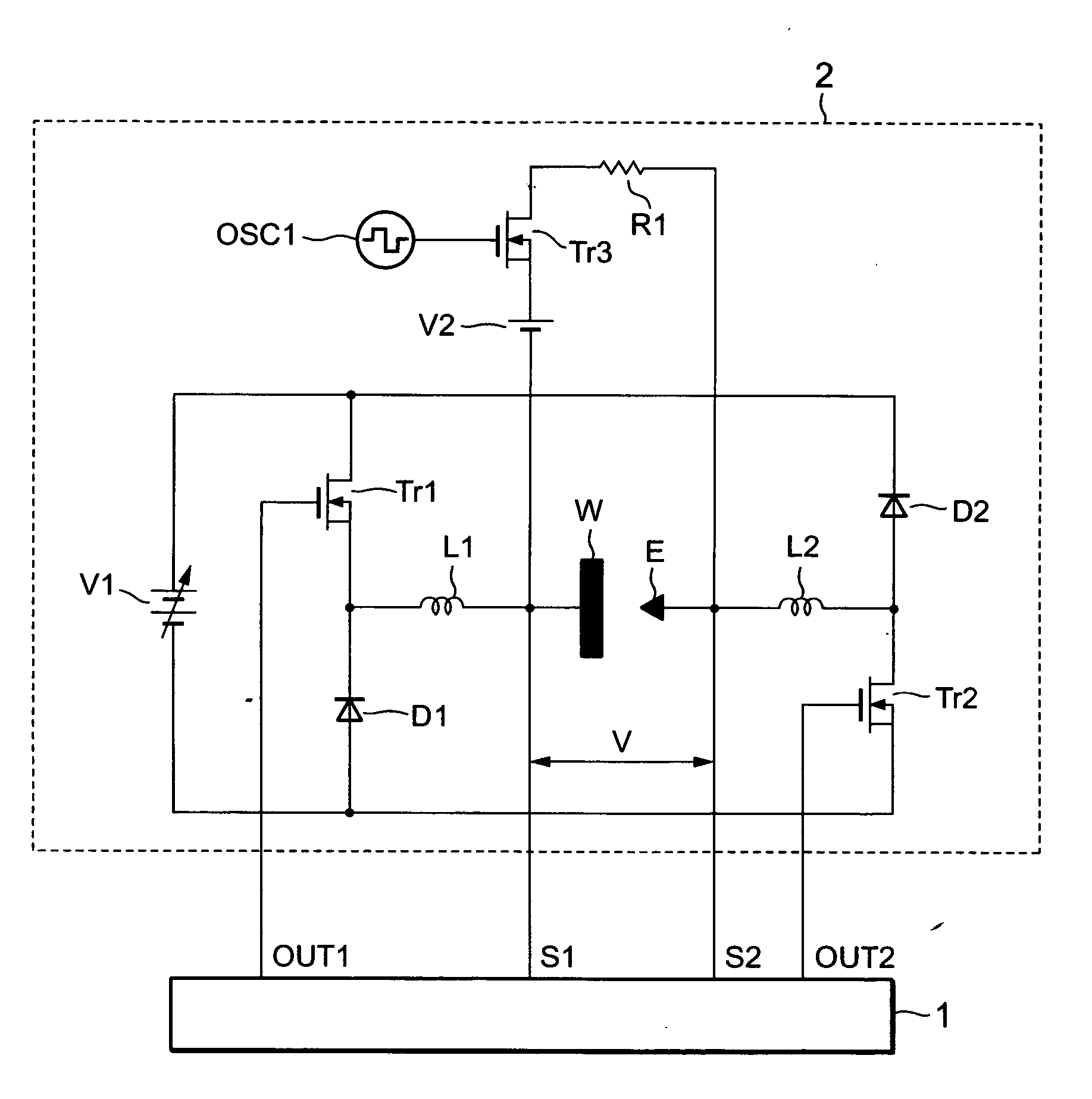
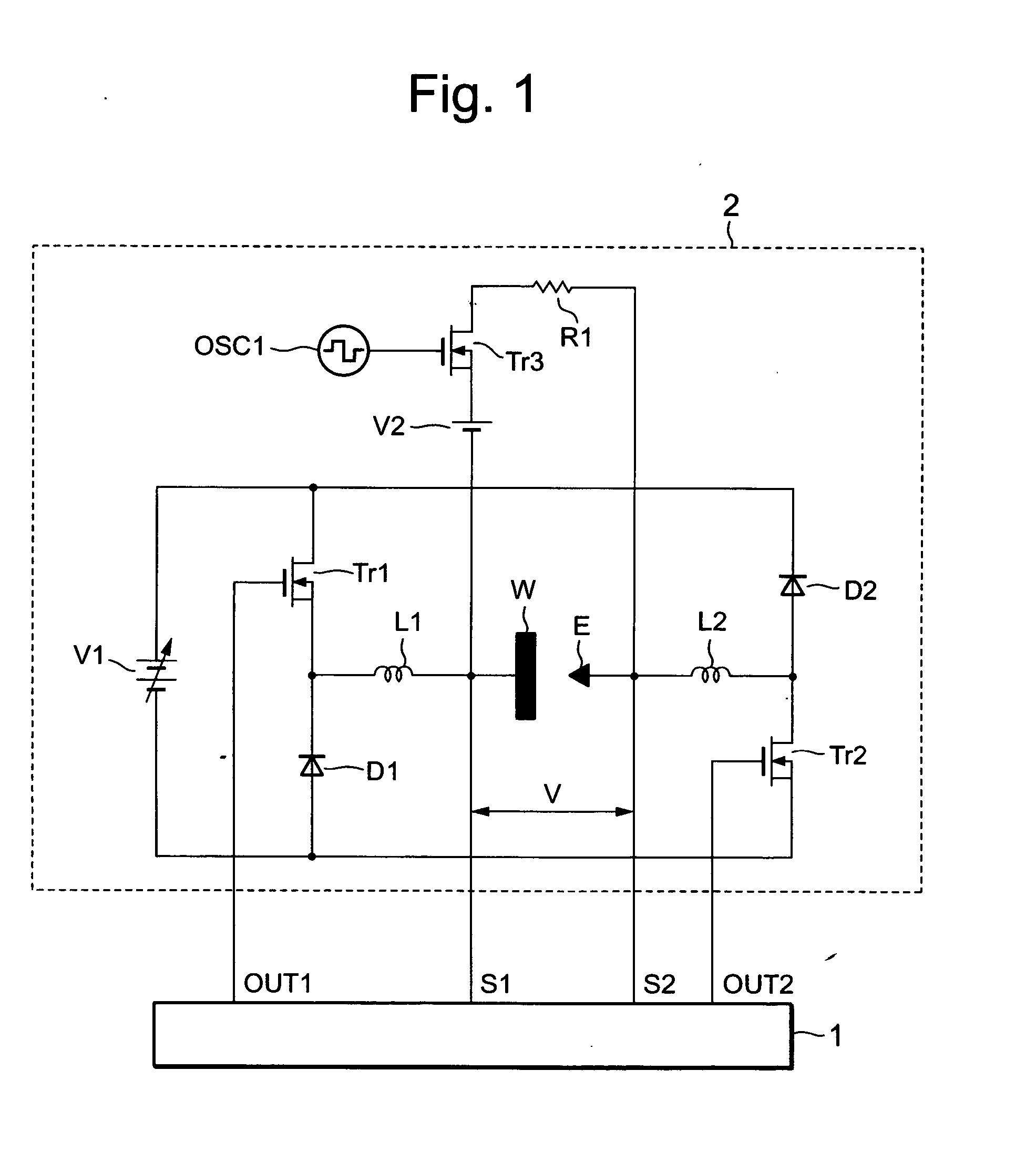
FIG. 1 is a configuration diagram of a machining electrical power supply device for a wire electrical discharge machining apparatus related to Embodiment 1 of this invention. In the figure, reference numeral 1 is a machining electrical power supply control circuit, 2 is a machining electrical power supply circuit, E is a wire electrode, W is a workpiece, V represents inter-electrode voltage between the wire electrode E and the workpiece W, OSC1 is an oscillator, Tr1 is a switching element that performs ON-OFF operations by means of a drive signal OUT1 output from the machining power supply control circuit 1, Tr2 is a switching element that performs ON-OFF operations by means of a drive signal OUT2 output from the machining power supply control circuit 1, Tr3 is a switching element that performs ON-OFF operations by means of an oscillation signal output from the oscillator OSC1, V1 is a variable-voltage direct current power supply, V2 is a direct current power supply, R1 is a resisto...

embodiment 2

FIG. 6 is a configuration diagram of the machining power control circuit 1 of the machining electrical power supply device for the wire electrical discharge machining apparatus related to Embodiment 2 of this invention, and the machining electrical power supply circuit 2 is similar to FIG. 1 of Embodiment 1.

In FIG. 6, reference numeral 3 is a numerical control device, 5a is a pulse stretcher circuit, 6 is an electrical discharge state distinguishing circuit, 16 is a clock generator, 17a is a first counter, 17b is a first pulse agreement comparator circuit, 17c is a first pulse width setting circuit, 18a is a second counter, 18b is a second agreement comparator circuit, 18c is a second pulse width setting circuit, 19a is an OFF counter, 19b is an OFF counter agreement comparator circuit, 19c is an OFF time setting circuit, 20, 21 and 22 are latches, 23, 24 and 25 are flip-flops, OUT1 is an ON-OFF operator drive signal for a switching element Tr1 of the machining electrical power su...

embodiment 3

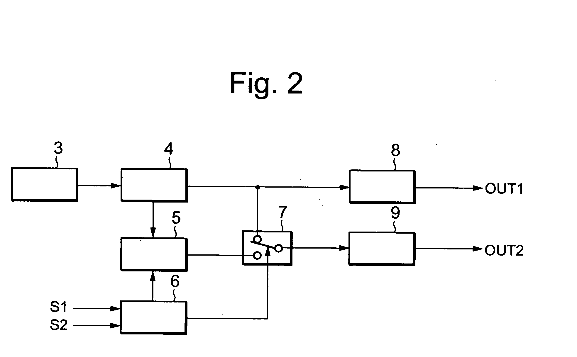
FIG. 8 is a configuration diagram of the machining electrical power supply control circuit 1 of the machining electrical power supply device for the wire electrical discharge machining apparatus according to Embodiment 3 of this invention, and the machining electrical power supply circuit 2 is similar to FIG. 1 of Embodiment 1. Further, numerical references identical to FIG. 2 of Embodiment 1 indicate identical or equivalent parts.

In FIG. 8, numerical reference 26 is a pulse stretcher range setting circuit, 27 is an all-waveforms output counter means for counting the output count of all waveforms, 28 is a trapezoidal wave output counter means for counting the output count of trapezoidal waves only, 29 is a reset circuit for resetting counter values at an optional cycle, 30 is a counting circuit for performing calculations according to the output of the all-waveforms output counter means 27 and the trapezoidal wave output counter means 28.

OUT1—the output signal of the first signa...


PUM

PropertyMeasurementUnit
clock frequencyaaaaaaaaaa
frequencyaaaaaaaaaa
electrical poweraaaaaaaaaa

Abstract

Machining electrical power supply device for wire electrical discharge machining. Includes an electrical discharge state distinguishing circuit (6) for distinguishing at least two inter-electrode states, including electrical shorting and normal electrical discharge, between a wire electrode (E) and a workpiece (W), and an inter-electrode current waveform control means for supplying, and for switching between supply of, a triangular wave and a trapezoidal wave current to the electrodes. According to the inter-electrode state distinguished by the electrical discharge state distinguishing circuit (6), in cases where the inter-electrode state is that of electrical shorting (Y1), the inter-electrode current waveform control means supplies a triangular wave current (I) to the electrodes, and in cases where the inter-electrode state is that of normal electrical discharge (Y3), it supplies a trapezoidal wave current (I) to the electrodes. Breakage of the wire electrode (E) can be avoided and machining speed can be improved.

Description

TECHNICAL FIELD The present invention relates to improvement in machining electrical power supply devices used in wire electrical discharge machines that machine a workpiece by electrical discharge between a wire electrode and the workpiece. BACKGROUND ART In wire electrical discharge machining, insulating machining-fluid is put between a wire electrode and a workpiece as electrodes, and while the wire electrode and the workpiece are moved relative to one another, machining electrical power is supplied to the electrodes by a machining electrical power supply device, and the workpiece is machined by electrical discharge energy. An example of this type of machining electrical power supply device in a conventional wire electrical discharge machine that uses wire electrical discharge machining is disclosed in Japanese Laid-Open Patent Publication 1996-118147. This machining electrical power supply device is provided with an electrical shorting distinguishing circuit for distinguishin...

Claims


Application Information

Patent Timeline
Patent Type & Authority Applications(United States)
IPC IPC(8): B23H1/02B23H7/04
CPCB23H7/04B23H1/022
Inventor SATOU, SEIJIOOGURO, HIROYUKIYAMADA, HISASHI
Owner MITSUBISHI ELECTRIC CORP
Learn More