Aluminide or chromide coating of turbine engine rotor component

a technology of turbine engines and rotor components, applied in the direction of solid-state diffusion coating, chemical vapor deposition coating, machines/engines, etc., can solve the problems of premature removal and replacement accelerated corrosion, and increased concern for oxidation and corrosion of disks and seal elements

Inactive Publication Date: 2005-03-10
GENERAL ELECTRIC CO
View PDF13 Cites 47 Cited by
  • Summary
  • Abstract
  • Description
  • Claims
  • Application Information

AI Technical Summary

Problems solved by technology

As a result, oxidation and corrosion of the disks and seal elements have become of greater concern.
Alkaline sulfate deposits resulting from ingested dirt and sulfur in the combustion gas are a major source of the corrosion, but other elements in the aggressive combustion and bleed gas environment may also accelerate the corrosion.
The oxidation and corrosion damage may lead to premature removal and replacement of the disks and seal elements unless the damage is reduced or repaired.
They have resistance to oxidation and corrosion damage, but that resistance is not sufficient to protect them at the operating temperatures now being reached.
Disks and other rotor components made from newer generation alloys may also contain lower levels of aluminum and chromium, and may be more susceptible to corrosion attack.
These turbine blade coatings are generally too thick and heavy for use on disks and seal elements, and also may adversely affect the fatigue life of the disks and seal elements.

Method used


Image

  • Aluminide or chromide coating of turbine engine rotor component
  • Aluminide or chromide coating of turbine engine rotor component
  • Aluminide or chromide coating of turbine engine rotor component

Examples


example 1

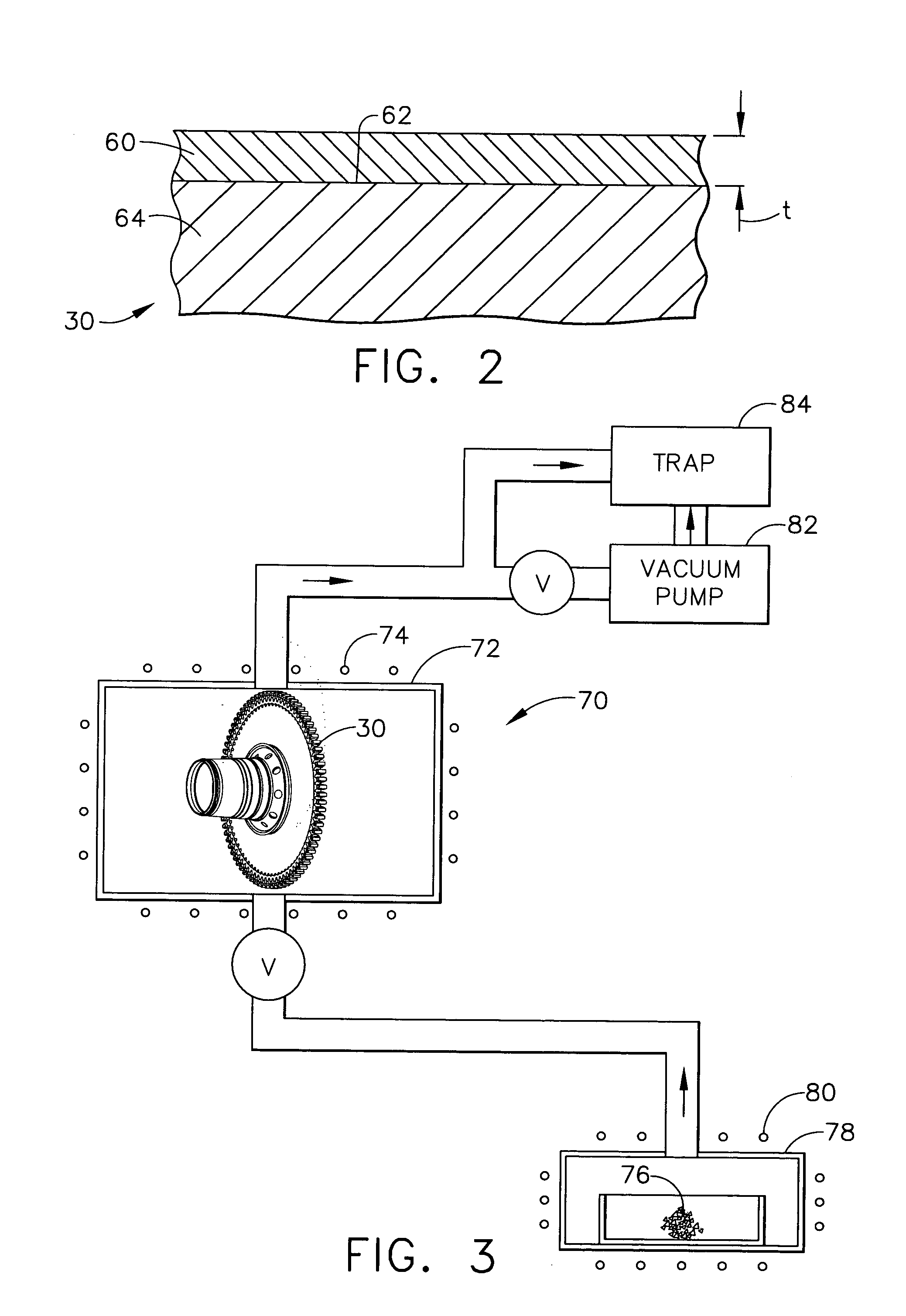
[0053] A process of the invention is used to form an aluminide coating on turbine disks in the coating container shown in FIG. 3. The disks are loaded into the coating container and heated to a temperature of about 270° C. A tri-n-butyl aluminum coating gas is then flowed into the coating container at a pressure of about 500 mtorr (about 6.8 kgf / m2) for about 5 hours to force the aluminum coating vapors to flow around the disks, thereby depositing an aluminum coating on the surface of the disks. The thickness of the aluminum coating is controlled by the temperature, gas flow, and elapsed time of the gas flow. The coated disks are then heated in a vacuum to a temperature of about 670° C. for about 5 hours to form an aluminide coating on the surface of the disks. The disks are then heated to a temperature of about 700° C. for 8 hours in the presence of oxygen at a partial pressure of about 10−3 torr (about 13.6 gf / m2) to form an oxide protective coating on the surface of the disks. Th...

example 2

[0054] A process of the invention is used to form an aluminide coating on turbine disks in the coating container shown in FIG. 3. The disks are loaded into the coating container and heated to a temperature of about 450° C. A tri-n-butyl aluminum coating gas is then flowed into the coating container at a pressure of about 100 mtorr (about 1.4 kgf / m2) for about 1 hour to force the aluminum coating vapors to flow around the disks, thereby depositing an aluminum coating on the surface of the disks. The thickness of the aluminum coating is controlled by the temperature, gas flow, and elapsed time of the gas flow. The coated disks are then heated in a vacuum to a temperature of about 670° C. for about 1 hour to form an aluminide coating on the surface of the disks. The disks are then heated to a temperature of about 700° C. for 8 hours in the presence of oxygen at a partial pressure of about 10−3 torr (about 13.6 gf / m2) to form an oxide protective coating on the surface of the disks. The ...

example 3

[0055] A process of the invention is used to form an chromide coating on turbine disks in the coating container shown in FIG. 3. The disks are loaded into the coating container and heated to a temperature of about 600° C. A hexacarbonyl chromium coating gas is then flowed into the coating container at a pressure of about 1000 mtorr (about 14 kgf / m2) for about 1 hour to force the chromium coating vapors to flow around the disks, thereby depositing an chromium coating on the surface of the disks. The thickness of the chromium coating is controlled by the temperature, gas flow, and elapsed time of the gas flow. The coated disks are then heated in a vacuum to a temperature of about 670° C. for about 1 hour to form an chromide coating on the surface of the disks. The disks are then heated to a temperature of about 700° C. for 8 hours in the presence of oxygen at a partial pressure of about 10−3 torr (about 13.6 gf / m2) to form an oxide protective coating on the surface of the disks. The o...


PUM

PropertyMeasurementUnit
temperatureaaaaaaaaaa
operating temperatureaaaaaaaaaa
thicknessaaaaaaaaaa

Abstract

A turbine engine rotor component, such as a compressor or turbine disk or seal element, is protected from corrosion by depositing an aluminum or chromium coating on the component. The deposition can be performed by a vapor deposition process, such as metal organic chemical vapor deposition (MOCVD), to a coating thickness of from about 0.2 to about 50 microns, typically from about 0.5 to about 3 microns. In one embodiment, the method is conducted in a vapor coating container having a hollow interior coating chamber, and includes the steps of loading the coating chamber with the component to be coated; and flowing a tri-alkyl aluminum or chromium carbonyl coating gas into the loaded coating chamber at a specified temperature, pressure, and time to deposit an aluminum or chromium coating on the surface of the component. The coated component is then heated in a nonoxidizing atmosphere to a specified temperature to form an aluminide or chromide coating on the surface. The coated component is typically then heated or maintained at an elevated temperature in the presence of oxygen to form an oxide coating on the surface of the component.

Description

BACKGROUND OF THE INVENTION [0001] The present invention relates to a method for forming a protective coating on a turbine engine component. More particularly, the invention relates to forming an aluminide or chromide coating on the surface of a turbine engine rotor component, such as a compressor or turbine disk, seal element or shaft. The coated component is typically then heated or maintained at an elevated temperature in the presence of oxygen to form a protective oxide coating on the surface of the component. The invention also relates to such a coated rotor component. [0002] In an aircraft gas turbine engine, air is drawn into the front of the engine, compressed by a shaft-mounted compressor, and mixed with fuel. The mixture is burned, and the hot exhaust gases are passed through a turbine mounted on the same shaft. The flow of combustion gas turns the turbine by impingement against the airfoil section of the turbine blades, which turns the shaft and provides power to the comp...

Claims


Application Information

Patent Timeline
Patent Type & Authority Applications(United States)
IPC IPC(8): C23C10/02C23C16/16C23C16/20F01D5/28
CPCC23C10/02C23C16/16C23C16/20F05D2300/611Y02T50/67F05D2230/90F01D5/288Y02T50/60
Inventor ACKERMAN, JOHN FREDERICKWEIMER, MICHAEL JAMESHEANEY, JOSEPH ALOYSIUSZIMMERMAN, ROBERT GEORGE JR.NAGARAJ, BANGALORE ASWATHAHAZEL, BRIAN THOMASDAS, NRIPENDRA NATH
Owner GENERAL ELECTRIC CO
Why Eureka
Try Eureka