Devices, systems, and methods for reshaping a heart valve annulus
Active Publication Date: 2005-03-10
VENTURE LENDING & LEASING IV
View PDF75 Cites 466 Cited by
Summary
Abstract
Description
Claims
Application Information
AI Technical Summary
This helps you quickly interpret patents by identifying the three key elements:
Problems solved by technology
Method used
Benefits of technology
[0043] In one embodiment, the devices, systems, and methods install the anchor structure within the great cardiac vein adjacent a length comprising at least a portion of a posterior annulus of the mitral valve. The devices, systems, and methods couple a posterior region of an implant to the anchor structure within great cardiac vein and extend the implant across the left atrium, through an interatrial septum, and into a right atrium. The devices, systems, and methods tension the implant and anchor an anterior region of the implant to tissue in or near the right atrium to maintain the tension. The tension applied by the implant can improve septal-to-lateral dimensions of the valve and thereby lead to improved leaflet coaption to ameliorate functional mitral valve regurgitation. In the case of organic mitral valve regurgitation, the tension applied by the implant can serve the stabilize the posterior annulus in the manner of an annuloplasty ring, to resist change in annulus size during the cardiac cycle.
[0044] In one embodiment, t
Problems solved by technology
Valve malfunction can result from the chordae tendineae (the chords) becoming stretched, and in some cases tearing.
When a chord tears, the result is a leaflet that flails.
Also, a normally structured valve may not function properly because of an enlargement of or shape change in the valve annulus.
This condition is referred to as a dilation of the annulus and generally results from heart muscle failure.
In addition, the valve may be defective at birth or because of an acquired disease.
As a result, an undesired back flow of blood from the left ventricle into the left atrium can occur.
First, blood flowing back into the atrium may cause high atrial pressure and reduce the flow of blood into the left atrium from the lungs.
As blood backs up into the pulmonary system, fluid leaks into the lungs and causes pulmonary edema.
Second, the blood volume going to the atrium reduces volum
Method used
Image
Click on the blue label to locate the original text in one second.
Reading with bidirectional positioning of images and text.
Examples
Embodiment Construction
[0096] Although the disclosure hereof is detailed and exact to enable those skilled in the art to practice the invention, the physical embodiments herein disclosed merely exemplify the invention, which may be embodied in other specific structure. While the preferred embodiment has been described, the details may be changed without departing from the invention, which is defined by the claims.
[0097] I. Trans-Septal Implants for Direct Shortening of the Minor. Axis of a Heart Valve Annulus
[0098] A. Implant Structure
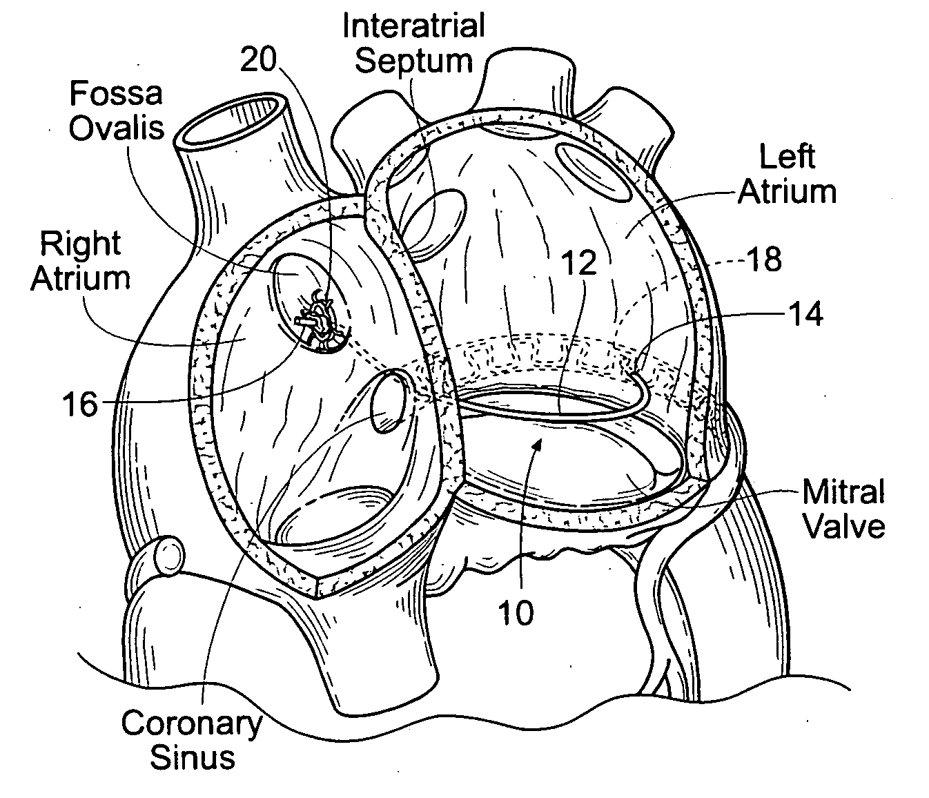
[0099]FIGS. 10A and 10B show embodiments of an implant 10 that is sized and configured to extend across the left atrium in generally an anterior-to-posterior direction, spanning the mitral valve annulus. The implant 10 comprises a spanning region or bridging element 12 having a posterior tissue anchoring region 14 and an anterior tissue anchoring region 16.
[0100] The posterior anchoring region 14 is sized and configured to be anchored in a region of atrial tissue above t...
PUM
Abstract
Implants or systems of implants apply a selected force vector or a selected combination of force vectors within or across the left atrium, which allow mitral valve leaflets to better coapt. The implants or systems of implants make possible rapid deployment, facile endovascular delivery, and full intra-atrial retrievability. The implants or systems of implants also make use of strong fluoroscopic landmarks.
Description
RELATED APPLICATIONS [0001] This application is a continuation-in-part of co-pending U.S. patent application Ser. No. 10 / 677,104, filed Oct. 1, 2003, and entitled “Devices, Systems, and Methods for Reshaping a Heart Valve Annulus,” which claims the benefit of U.S. patent application Ser. No. 09 / 666,617, filed Sep. 20, 2000 and entitled “Heart Valve Annulus Device and Methods of Using Same,” which is incorporated herein by reference. This application also claims the benefit of Patent Cooperation Treaty Application Serial No. PCT / US02 / 31376, filed Oct. 1, 2002 and entitled “Systems and Devices for Heart Valve Treatments,” which claimed the benefit of U.S. Provisional Patent Application Ser. No. 60 / 326,590, filed Oct. 1, 2001, which are incorporated herein by reference. This application also claims the benefit of U.S. Provisional Application Ser. No. 60 / 429,444, filed Nov. 26, 2002, and entitled “Heart Valve Remodeling Devices;” U.S. Provsional Patent Application Ser. No. 60 / 429,709, f...
Claims
Application Information
Patent Timeline
Application Date:The date an application was filed.
Publication Date:The date a patent or application was officially published.
First Publication Date:The earliest publication date of a patent with the same application number.
Issue Date:Publication date of the patent grant document.
PCT Entry Date:The Entry date of PCT National Phase.
Estimated Expiry Date:The statutory expiry date of a patent right according to the Patent Law, and it is the longest term of protection that the patent right can achieve without the termination of the patent right due to other reasons(Term extension factor has been taken into account ).
Invalid Date:Actual expiry date is based on effective date or publication date of legal transaction data of invalid patent.