Piezoelectric vibration energy harvesting device and method

a piezoelectric and vibration energy technology, applied in piezoelectric/electrostrictive/magnetostrictive devices, piezoelectric/electrostriction/magnetostriction machines, electrical apparatus, etc., can solve the problem of low conversion efficiency from vibration energy to electric energy, low efficiency of vibration energy conversion, and bulky piezoelectric structure in flexural mode, etc. problem, to achieve the highest piezoelectric coupling coefficient, high efficiency of vibration energy extraction

Inactive Publication Date: 2005-03-17
WILCOXON RES
View PDF6 Cites 25 Cited by
  • Summary
  • Abstract
  • Description
  • Claims
  • Application Information

AI Technical Summary

Benefits of technology

[0005] It is therefore an object of the invention to efficiently harvest vibration kinetic energy from the ambient environment or machinery and store it in the form of electric energy, which later is used to power an electronic device. A highly efficient, small size vibration harvesting device will enable a self-powered, truly wireless transducer system.
[0006] By using the state-of-the-art relaxor single crystal, which exhibits the highest piezoelectric coupling coefficient, and a compression-tension, piezoelectric composite, cymbal structure, a compact, highly efficient vibration energy extracting device is accomplished. Moreover, before connecting the stack with a rectifier/storage circuit, an inductor L is introduced which is parallel with the piezoelectric stack. The resonance of the LC loop is tuned around the resonance of the stack. This inductor will greatly improve the electric energy transferring efficiency.
[0007] The major difference between the prior art and this design is in the piezoelectric transduction structure. Instead of using a flexural plate or beam, the ne

Problems solved by technology

The flexural mode piezoelectric effect (d31 mode) is very inefficient; this results in a low conversion efficiency from vibration energy to electric energy (less than 10%).
B

Method used


Image

  • Piezoelectric vibration energy harvesting device and method
  • Piezoelectric vibration energy harvesting device and method
  • Piezoelectric vibration energy harvesting device and method

Examples


Embodiment Construction

[0012] A preferred embodiment of the present invention will now be set forth in detail, including two circuits incorporating it.

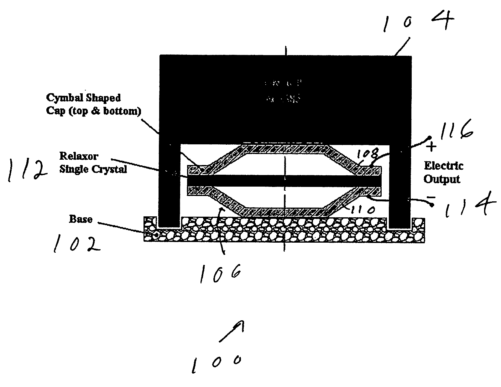
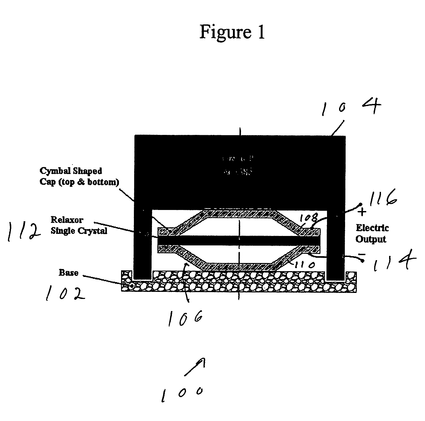
[0013]FIG. 1 shows an energy harvesting device 100. The device includes a base 102 and a proof mass 104. Disposed between the base 102 and the proof mass 104 is a cymbal stack 106 including top and bottom cymbal-shaped caps 108, 110 sandwiching a relaxor single crystal 112. The cymbal-shaped caps are connected to electrodes 114, 116 forming an electric output.

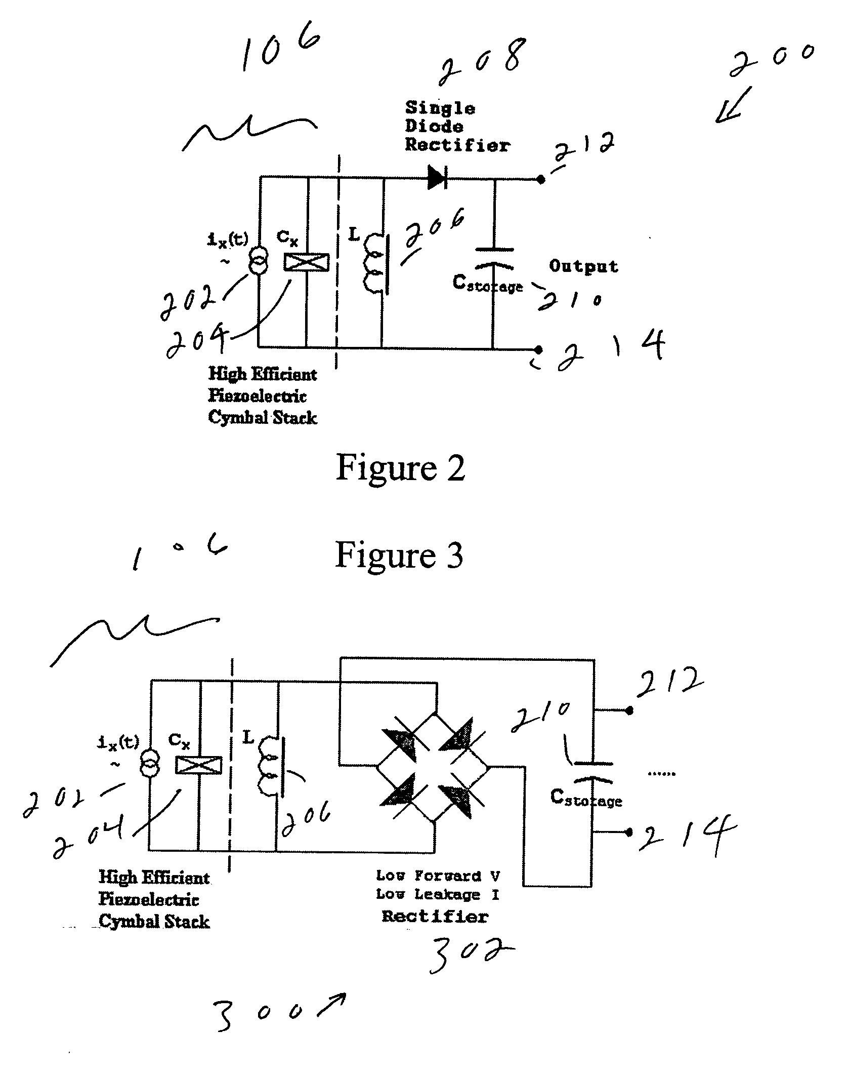
[0014]FIG. 2 shows a first circuit 200 incorporating the energy harvesting device 100. In the circuit diagram of FIG. 2, the cymbal stack 106 is represented by an equivalent circuit comprising a current source 202 and a capacitor 204. Connected in parallel across the output of the cymbal stack is an inductor 206. A single diode rectifier 208, a storage capacitor 210 and output electrodes 212, 214 complete the circuit 200.

[0015]FIG. 3 shows a second circuit 300 incorporating the energy harvesting dev...


PUM


Abstract

A piezoelectric vibration energy harvesting device which is made up of a base, a proof mass, and a cymbal stack disposed between the base and the proof mass. The cymbal stack has a piezoelectric element disposed between the base and the proof mass, a first cymbal-shaped cap disposed between the proof mass and the piezoelectric crystal, and a second cymbal-shaped cap disposed between the piezoelectric crystal and the base.

Description

STATEMENT OF GOVERNMENT INTEREST [0001] The work leading to the present invention was supported in party by Naval Surface Warfare Center Dahlgren Division (NSWCDD) Contract Number: N00178-03-C-3056. The government has certain rights in the invention.FIELD OF THE INVENTION [0002] The present invention is directed to a highly efficient, small size, vibration harvesting and electric energy storage device. The energy level is high enough to power a wireless sensor. DESCRIPTION OF RELATED ART [0003] Current technology utilizes a flexural, piezoelectric composite bending structure as a vibration energy to electric energy transducer. The selected piezoelectric materials are PZT ceramics or PVDF polymer. The output of this device is connected to an AC-DC converter which is typically composed of a diode rectifier with a storage capacitor. [0004] The flexural mode piezoelectric effect (d31 mode) is very inefficient; this results in a low conversion efficiency from vibration energy to electric...

Claims


Application Information

Patent Timeline
IPC IPC(8): H01L41/113
CPCH02N2/186
Inventor DENG, KEN KAN
Owner WILCOXON RES
Why Eureka
Try Eureka