

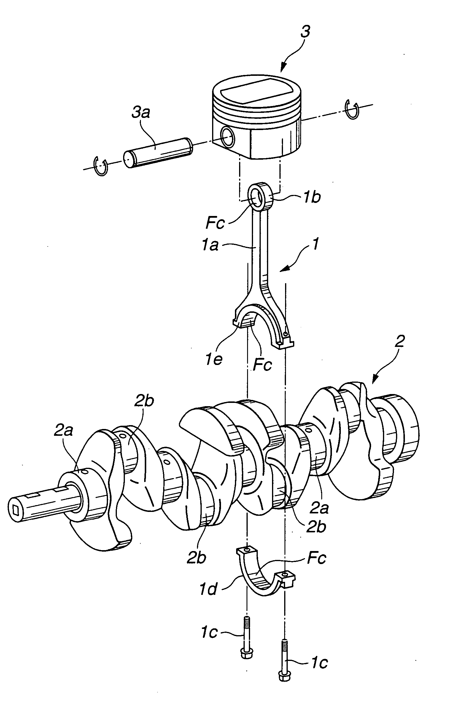
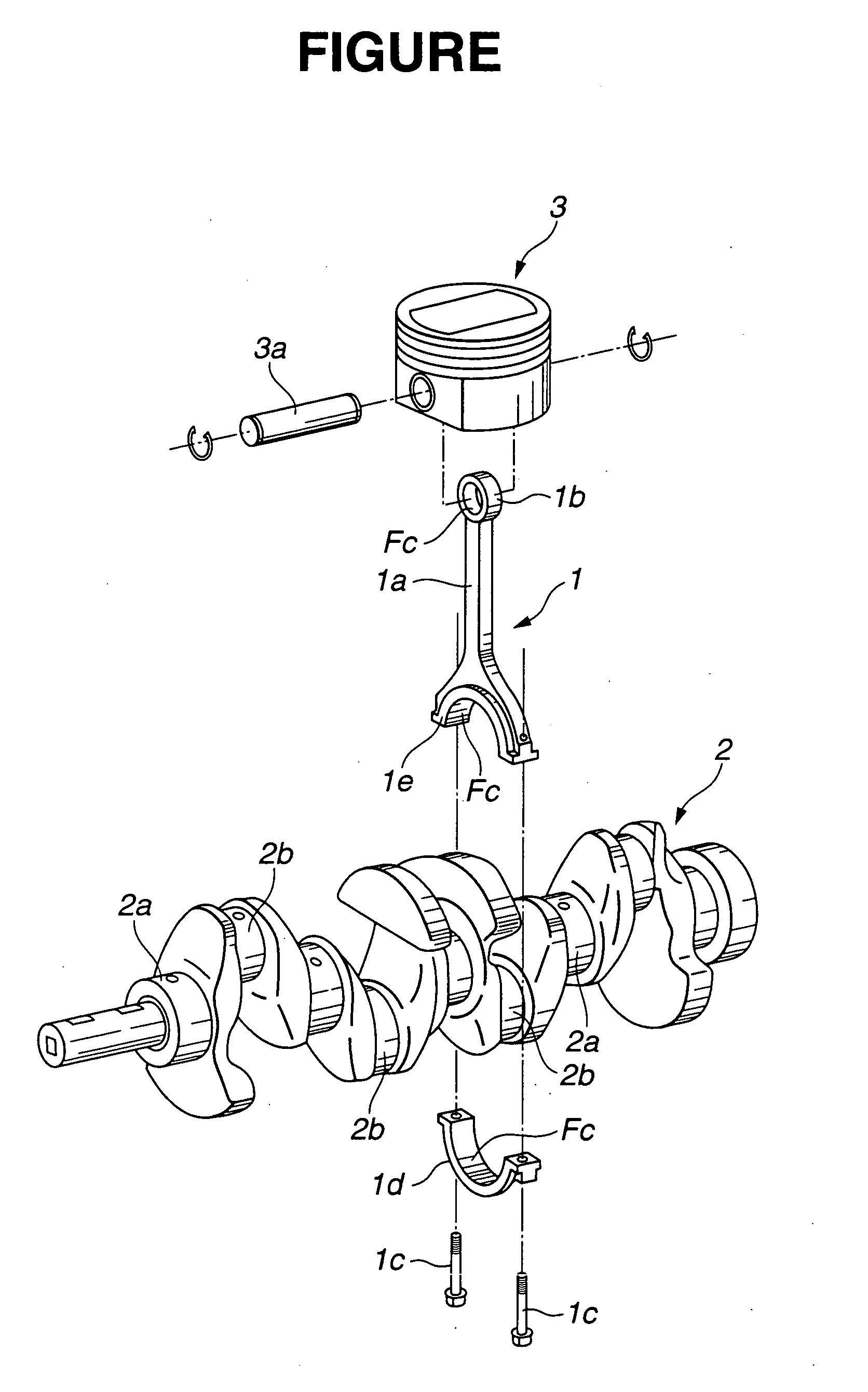
Structure for connecting piston to crankshaft
- Summary
- Abstract
- Description
- Claims
- Application Information
AI Technical Summary
Benefits of technology
Problems solved by technology
Method used
Image

Examples
example 1
[0064] A substantially-semicylindrical base block having a dimension of 8×12×40 mm (with a semicylindrical portion formed at a radius of 20 mm) was first cut from an aluminum alloy material AC8A according to JIS H5202. It should be noted that the aluminum alloy material AC8A is commonly used as a connecting rod material. A DLC coating film having a hydrogen content of 0.2 atomic %, a Knoop hardness Hk of 2170 kg / mm2, a maximum height surface roughness Ry (=Rmax) of 0.03 μm and a thickness of 0.5 μm was formed on the semicylindrical portion of the base block by a PVD arc ion plating process, thereby giving a test piece. Herein, the surface roughness Ry is explained as Rz according to JIS B0601.
[0065] Next, a plate-shaped block having a dimension of 8×12×40 mm was cut from iron casting FC250 (FCA) according to JIS G5501 and finished to give an opposite piece with a sliding surface controlled to a center line surface roughness Ra of 0.1 μm. The surface roughness Ra is herein explained...
example 2-8
[0067] The same test pieces and the same opposite pieces as used in Example 1 were prepared. Then, the test pieces and the opposite pieces were subjected to the friction / wear test using lubricating oils A-G.
PUM
 Abstract
Description
Claims
Application Information