Method for bonding a sputter target to a backing plate and the assembly thereof

a technology of sputter target and backing plate, which is applied in the direction of welding/cutting media/materials, manufacturing tools, and solvents. it can solve the problems of atoms or ions of the target material to be sputtered, limited use of sputtering target components in the bonding process, and large thermal energy imparted to the targ

Inactive Publication Date: 2005-03-24
PRAXAIR ST TECH INC
View PDF48 Cites 41 Cited by
  • Summary
  • Abstract
  • Description
  • Claims
  • Application Information

AI Technical Summary

Benefits of technology

[0014] Another object of the invention is to provide a solder bonded sputter target/backing pla

Problems solved by technology

Ion bombardment of the target not only causes atoms or ions of the target material to be sputtered, but imparts considerable thermal energy to the target.
Smooth surface diffusion bonding is an applicable method of bonding, but has only limited use in the bonding of sputtering target components.
Because the diffusion bond interfaces are planar, they are subject to stressing in simple shear which commonly leads to peeling away at the ends of the bond area.
The formation of brittle intermetallics at the bond interface, which increase in thickness with the associated long times of heat exposure, add to the potential of bond shear failure.
This feature causes disruption of the bond surface of the associated component during heated pressure application.
Groove bonding is applicable to bonding many dissimilar materials, but is limited to materials that have dissimilar melting temperatures because the process must occur near the melting temperature of the lower melting point alloy.
This precludes the use of this technique for similar metals.
It is also possible that the saw tooth nat

Method used


Image

  • Method for bonding a sputter target to a backing plate and the assembly thereof
  • Method for bonding a sputter target to a backing plate and the assembly thereof

Examples


Embodiment Construction

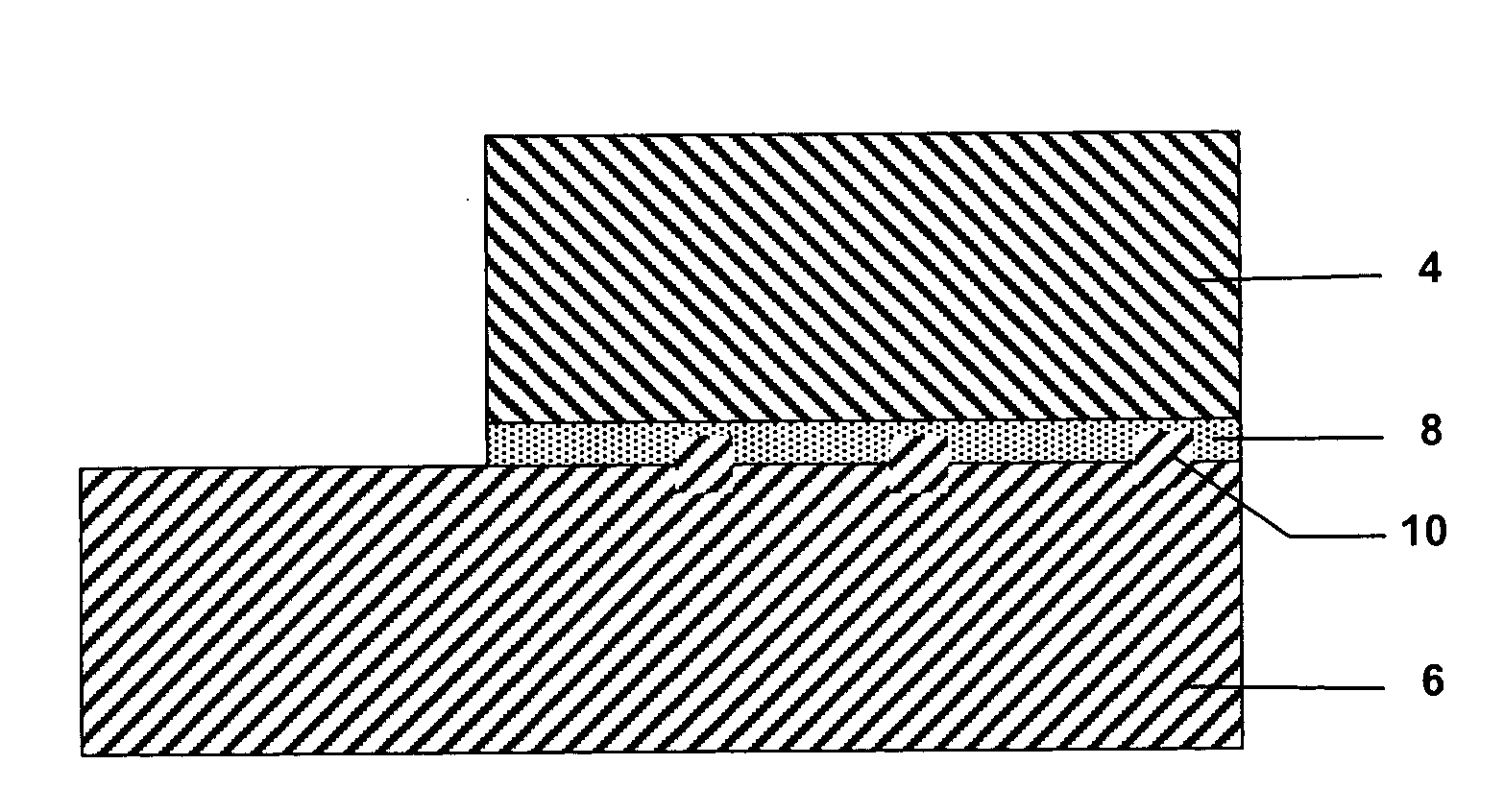
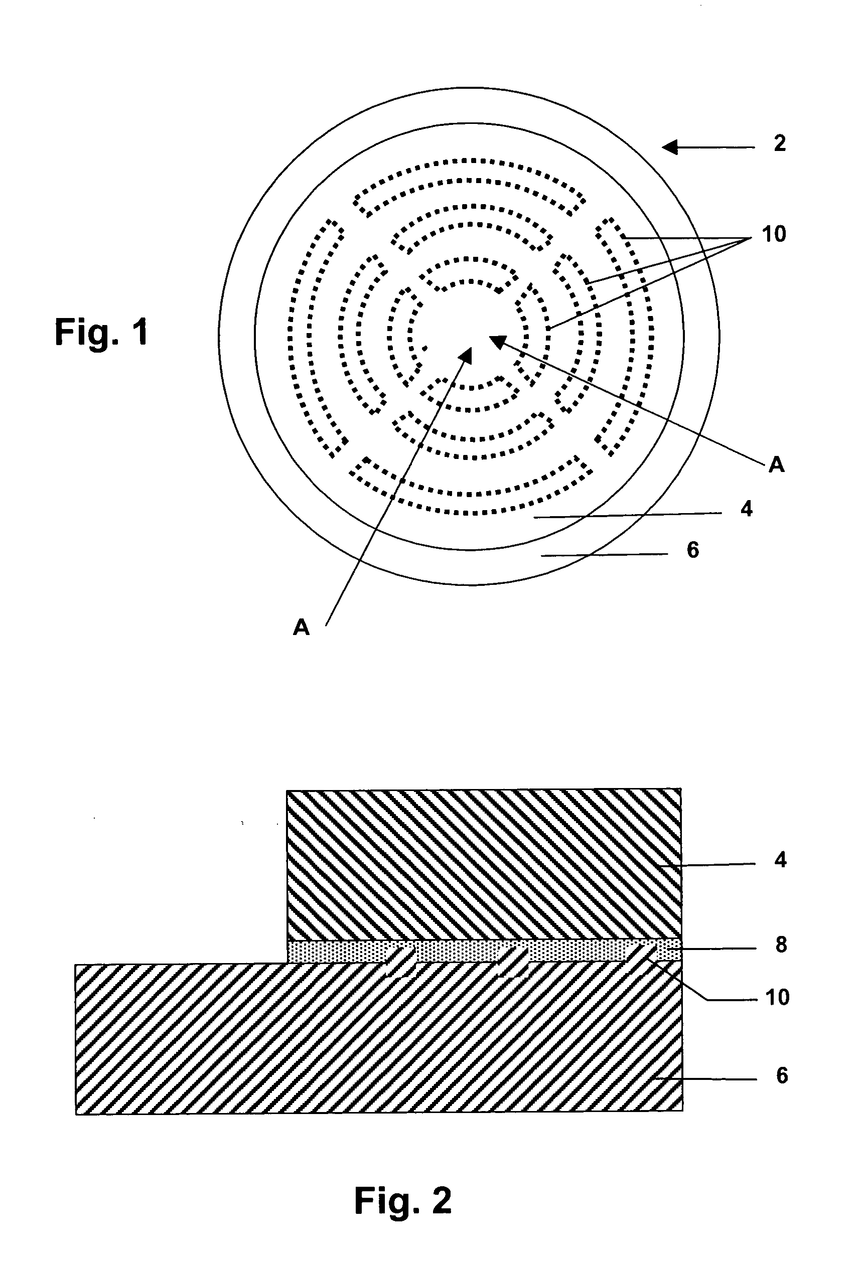
[0021] In the preferred embodiment of the invention, the solder bonded sputter target / backing plate assembly would be disc-shaped and have a plurality of segmented arcuate-shaped ridges spaced apart on different radii of the bonded surface of the disc-shaped backing plate. An alternate embodiment of the invention is to apply a plurality of segmented arcuate-shaped ridges spaced apart on different radii of the bonded surface of the disc-shaped sputter target backing plate. Preferably, the backing plate and ridges are made of the same material and the height of the ridges will be constant so that a uniform thickness solder bonded interface spacing can be achieved. For most applications, the height of the ridges could vary between about 0.005 inch and about 0.050 inch, preferably between about 0.010 inch and about 0.030 inch and most preferably about 0.020 inch. The spacing of the ridges has to be sufficient to prevent bowing of the sputter target at the center, especially for thinner ...


PUM

PropertyMeasurementUnit
Thicknessaaaaaaaaaa
Thicknessaaaaaaaaaa
Thicknessaaaaaaaaaa

Abstract

A method for solder bonding a sputter target to a backing plate having a plurality of spaced-apart ridges on its bonding surface to provide a uniform spacing and a uniform solder bonded interface; and the sputter target/backing plate assembly so produced.

Description

FIELD OF THE INVENTION [0001] The invention relates to a method of bonding a sputter target to a backing plate, and more specifically, the use of a backing plate having spaced-apart ridges on the bonding surface of the backing plate so that the ridges provide a uniform spacing between the target and backing plate and a uniform solder bonded interface. BACKGROUND OF THE INVENTION [0002] Cathodic sputtering is widely used for the deposition of thin layers of material onto desired substrates. Basically, this process requires a gas ion bombardment of a target having a face formed of a desired material that is to be deposited as a thin film or layer on a substrate. Ion bombardment of the target not only causes atoms or ions of the target material to be sputtered, but imparts considerable thermal energy to the target. This heat is dissipated beneath or around a backing plate that is positioned in a heat exchange relationship with the target. The target forms a part of a cathode assembly t...

Claims


Application Information

Patent Timeline
IPC IPC(8): B23K3/047
CPCB23K3/047H01J37/3423C23C14/3414H01J37/3435
Inventor HUNT, THOMAS J.KOENIGSMANN, HOLGER J.
Owner PRAXAIR ST TECH INC
Why Eureka
Try Eureka