

Low temperature alkaline fuel cell
a fuel cell, low temperature technology, applied in the direction of aqueous electrolyte fuel cells, cell components, electrochemical generators, etc., can solve the problems of fossil fuel pollution, global energy system movement, climate change,
- Summary
- Abstract
- Description
- Claims
- Application Information
AI Technical Summary
Benefits of technology
Problems solved by technology
Method used
Image

Examples
example 1
An alkaline fuel cell in accordance with the present invention was constructed and tested. The alkaline fuel cell included a hydrogen and oxygen electrode in accordance with the present invention. The hydrogen and oxygen electrode were contact with a potassium hydroxide solution.
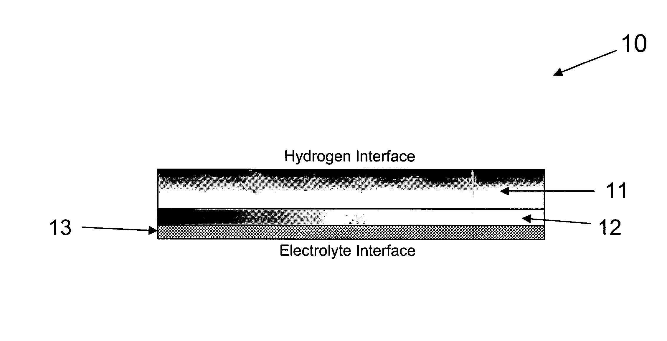
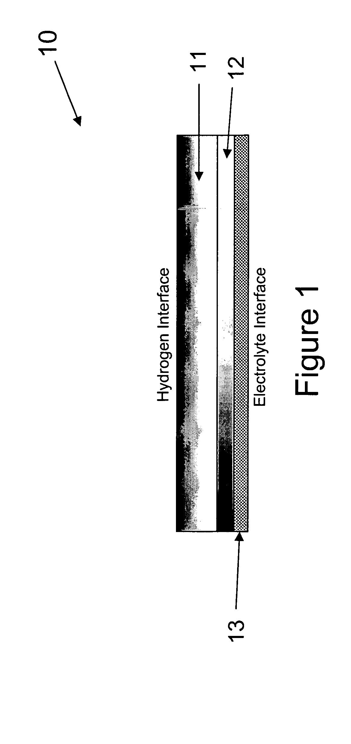
The hydrogen electrode of the alkaline fuel cell is composed of a gas diffusion layer and an active material layer. The gas diffusion layer of the hydrogen electrode is composed of a mixture of 60 weight percent Teflon and 40 weight percent Vulcan XC-72 carbon (Trademark of Cabot Corp.). The active material layer of the hydrogen electrode is composed of 52.8 weight percent Raney Nickel, 35.2 weight percent of the B1 alloy, 8 weight percent teflon, and 4 weight percent graphite. The gas diffusion layer and the active material layer were formed into ribbons and pressed between two current collector grids. The hydrogen electrode was then sintered at 325° C. for half an hour.
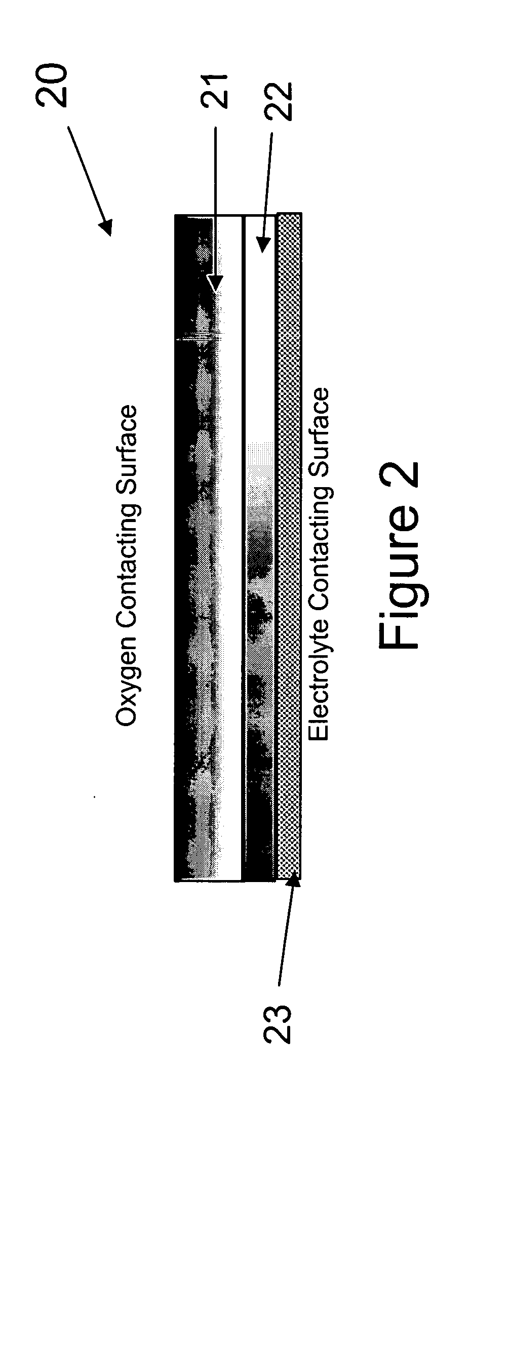
The oxygen electrode of the alka...
example 2
Three metal hydride negative electrodes in accordance with the present invention were prepared and tested at −30° C. The first negative electrode included the B0 alloy (control), the second electrode included the B1 alloy, and the third electrode included the B12 alloy. The metal hydride negative electrodes were standard compacted negative electrodes including either the B0, the B1, or the B12 alloy.
The charge transfer resistance (RCT) and double layer capacitance (Cdl) of the three electrodes were obtained through complex impedance measurements completed at −30° C. The results of the measurements are presented in FIG. 6, which shows the imaginary part (ZIm) of the complex impedance as a function of the real part (ZRE) of the complex impedance. The B0 alloy is represented by ▪, the B1 alloy is represented by ▴, and the B12 alloy is represented by ●. The charge transfer resistance (RCT) and double layer capacitance (Cdl) were obtained from the curves using standard electrochemical...
PUM
 Abstract
Description
Claims
Application Information