Method, apparatus, and circuit for record reproduction

a record reproduction and circuit technology, applied in the field of method, apparatus, circuit for recording reproduction, to achieve the effect of reducing the circuit size of the iterative decoder

Inactive Publication Date: 2005-03-24
FUJITSU LTD
View PDF7 Cites 31 Cited by
  • Summary
  • Abstract
  • Description
  • Claims
  • Application Information

AI Technical Summary

Benefits of technology

It is an object of the present invention to re

Problems solved by technology

Although the iterative method is more reliable than the PRML method, circuit scale of the encoder and the decoder i

Method used


Image

  • Method, apparatus, and circuit for record reproduction
  • Method, apparatus, and circuit for record reproduction
  • Method, apparatus, and circuit for record reproduction

Examples


Embodiment Construction

Exemplary embodiments of a magnetic disk apparatus as a representative of a record reproduction apparatus, and a method and a circuit for record reproduction will be explained below with reference to the accompanying drawings.

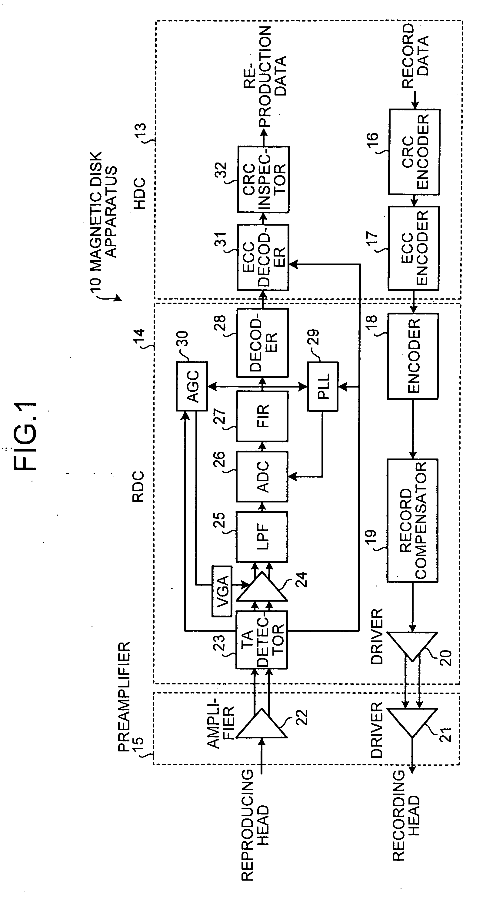
FIG. 1 is a general block diagram of a magnetic disk apparatus. The record reproduction system of the magnetic disk apparatus 10 includes a hard disk controller (HDC) 13, a read channel (RDC) 14, and a preamplifier 15.

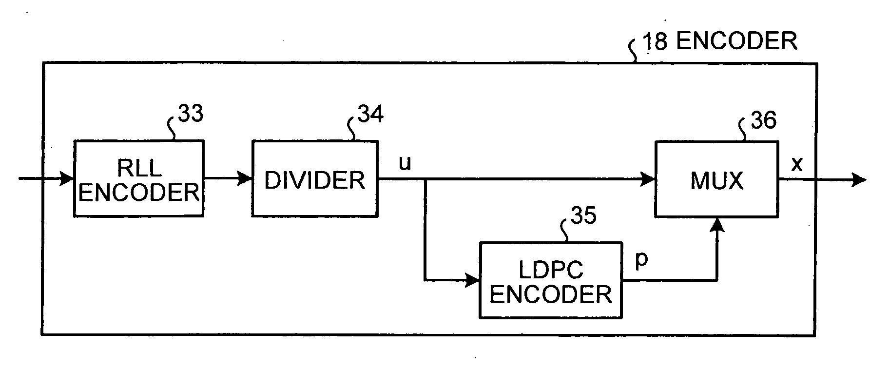
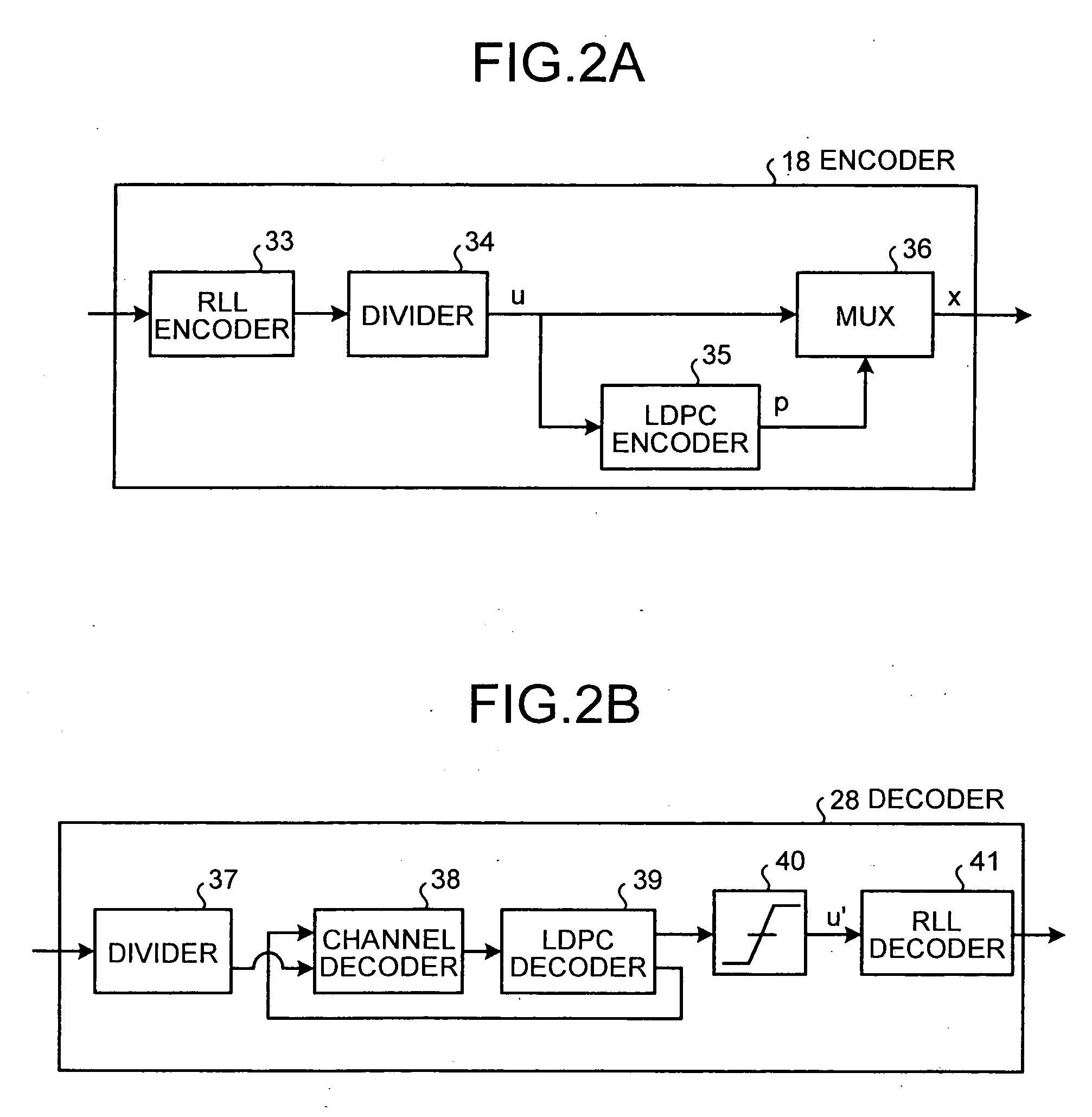
A cyclic redundancy check (CRC) encoder 16 and an ECC encoder 17 add parity to the record data within the HDC 13. A CRC code is used to detect an error of the ECC. The RDC 14 sends the record data to the preamplifier 15 via an encoder 18, a record compensator 19, and a driver 20. The encoder 18 executes an RLL encoding and a parity encoding. The record compensator 19 executes a compensation to slightly expand a transition interval at a portion where a magnetic transition is adjacent. The preamplifier 15 then makes a driver 21 generate a write ...


PUM


Abstract

A record reproduction apparatus includes an encoding unit that encodes sector data to be written into a recording medium, by dividing the data into a predetermined number of blocks, and an iterative decoding unit that iteratively decodes the sector data read from the recording medium, by dividing the sector data into the predetermined number of blocks.

Description

BACKGROUND OF THE INVENTION 1) Field of the Invention The present invention relates to a technology for performing error correction when reproducing recorded data. 2) Description of the Related Art Record reproduction apparatuses have a powerful error correcting function so that a signal can be reproduced without generation of an error. Only with such error correcting function it becomes possible to securely restore a signal from among unstable signals having noise. The error correcting function is realized by a combination of two methods: a partial response maximum likelihood (PRML) and an error correcting code (ECC). The PRML is a system that regards a recording channel as a partial response (PR) channel having an inter-symbol interference, and generally carries out a maximum likelihood detection using a Viterbi detector. The ECC corrects an error that cannot be corrected by the Viterbi detector, and generally uses Reed-Solomon (RS) codes (for example, refer to S. Lin and D. ...

Claims


Application Information

Patent Timeline
IPC IPC(8): G06F11/08G06F11/10G11B20/14G11B20/18H03M7/14H03M13/00H03M13/09H03M13/11H03M13/17H03M13/19
CPCG11B20/1833G11B20/1866G11B2020/1863H03M13/6325H03M13/1515H03M13/17H03M13/3746H03M13/1102
Inventor MORITA, TOSHIHIKOOHTA, MITSUHIKOSUGAWARA, TAKAO
Owner FUJITSU LTD
Why Eureka
Try Eureka