
Method for responding to sensor failures on egr/vgt engines

a technology for egr/vgt engines and sensors, applied in the direction of electric control, machines/engines, mechanical equipment, etc., can solve the problems of reducing emissions, reducing emissions, and reducing engine efficiency, so as to achieve efficient engine operation and emissions reduction, and maintaining a degree of control

Inactive Publication Date: 2005-03-31
DETROIT DIESEL CORP
View PDF10 Cites 22 Cited by
  • Summary
  • Abstract
  • Description
  • Claims
  • Application Information

AI Technical Summary

Benefits of technology

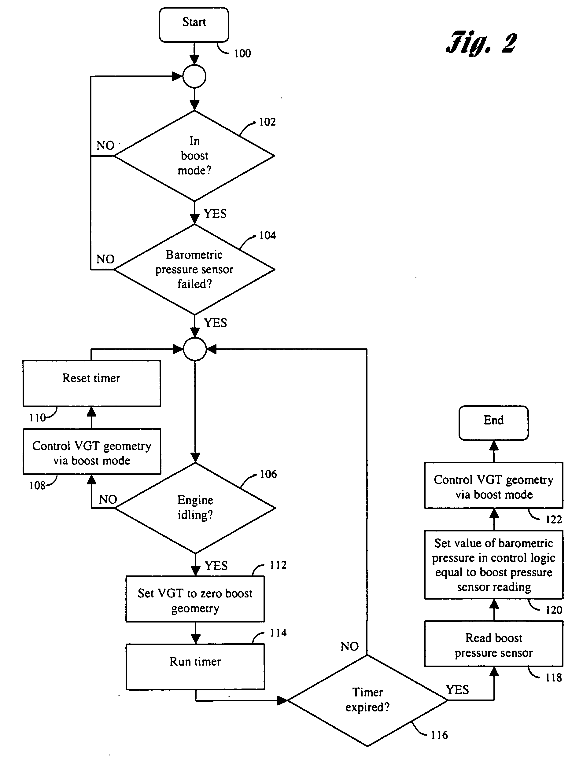
[0007] One object of the present invention is to provide a method for generating accurate substitute values for use by the engine control logic when EGR and VGT system-related sensors are diagnosed as having failed during operation.
[0008] Another object of the present invention is to provide a method for maintaining controlled performance of the VGT system in the face of sensor failures or mechanical faults associated with the EGR or VGT system.
[0010] A number of advantages are associated with the present invention. For example, the present invention provides a method for control of interrelated engine components that provides efficient engine operation and emissions reduction in the face of sensor failures and mechanical faults. In particular, the present invention provides a method for determining approximate values for failed sensors for use in the control logic, and for maintaining a degree of control over the EGR and VGT systems in the face of failed sensors and mechanical faults.

Problems solved by technology

Diagnosable malfunctions include both sensor failures and mechanical faults.
However, because these stored default values are inflexible imperfect approximations, emissions reduction and engine efficiency can suffer greatly.
When mechanical faults occur, continued error compensation attempts by the engine control logic typically force the variable geometry mechanism into either a completely open or completely closed position, also causing emissions reduction and engine efficiency to suffer.

Method used


Image

  • Method for responding to sensor failures on egr/vgt engines
  • Method for responding to sensor failures on egr/vgt engines
  • Method for responding to sensor failures on egr/vgt engines

Examples


Embodiment Construction

)

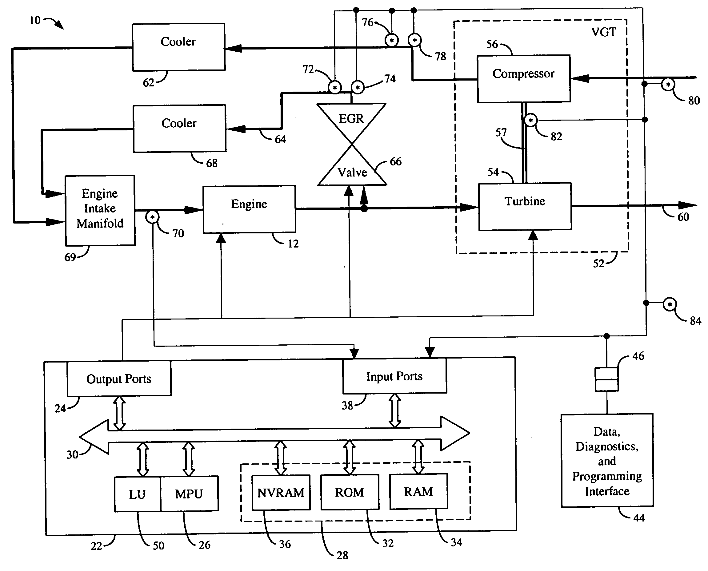
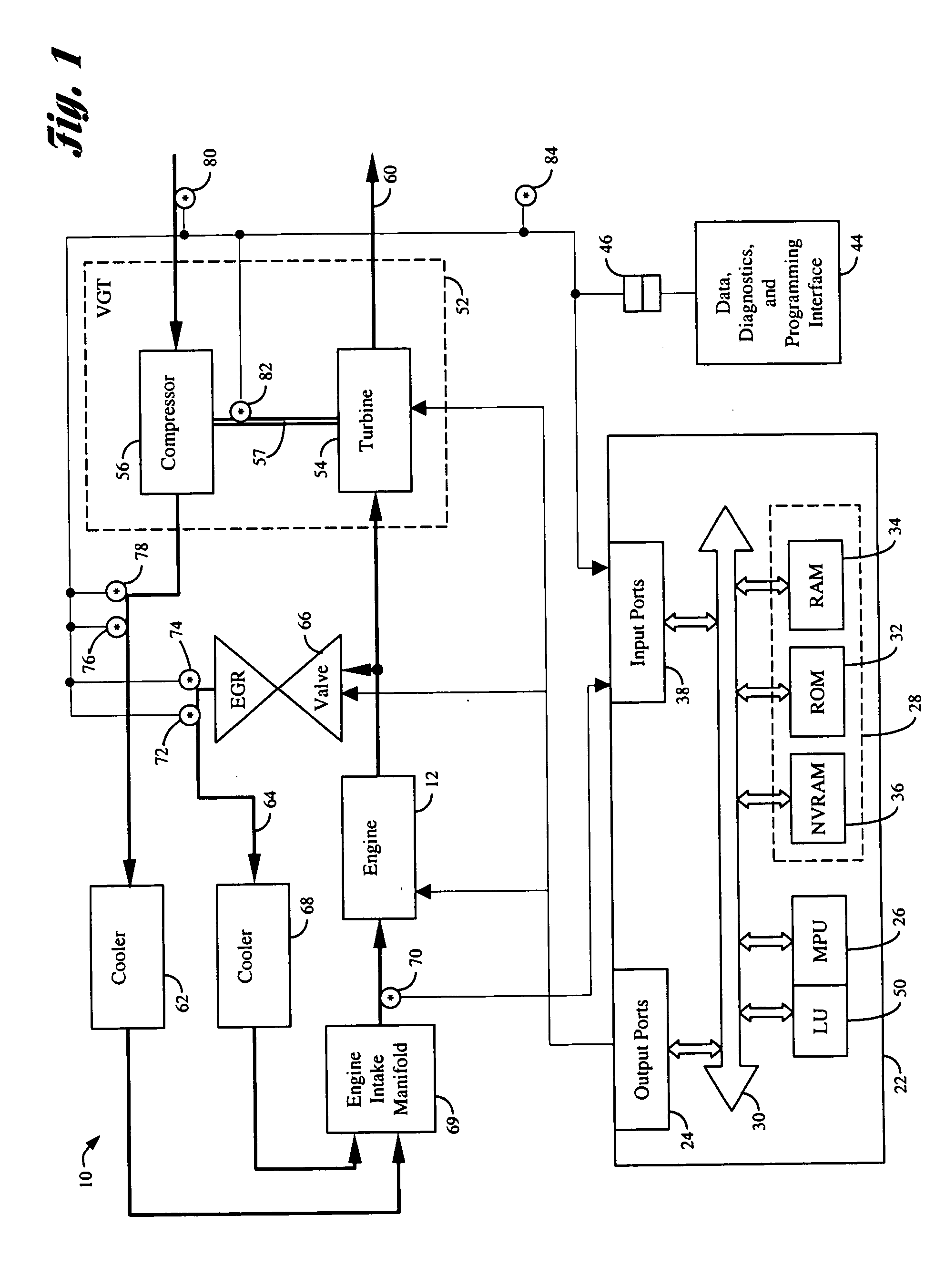
[0019] With reference to FIG. 1, an internal combustion engine and associated control systems and subsystems are generally indicated at 10. System 10 includes an engine 12 having a plurality of cylinders, each fed by a fuel injector. In a preferred embodiment, engine 12 is a compression-ignition internal combustion engine, such as a heavy duty diesel engine. The injectors receive pressurized fuel from a fuel supply in a known manner. Various sensors are in electrical communication with a controller 22 via input ports 38. Controller 22 preferably includes a microprocessor 26 in communication with various computer readable storage media 28 via data and control bus 30. Computer readable storage media 28 may include any of a number of known devices which function as read only memory 32, random access memory 34, and non-volatile random access memory 36.

[0020] Computer readable storage media 28 have instructions stored thereon that are executable by controller 22 to perform methods of c...


PUM


Abstract

A method for controlling an internal combustion engine having a variable geometry turbocharger (VGT) and an exhaust gas recirculation (EGR) system in the face of sensor failures and mechanical faults includes generating accurate substitute values for use by the engine control logic when EGR and VGT system-related sensors are diagnosed as having failed during operation, and maintaining controlled performance of the VGT system in the face of sensor failures or mechanical faults associated with the EGR or VGT system.

Description

BACKGROUND OF THE INVENTION [0001] 1. Field of the Invention [0002] The present invention relates to methods for the control of internal combustion engines with turbochargers and exhaust gas recirculation. [0003] 2. Background Art [0004] To improve performance, many internal combustion engines, particularly diesel engines, include a turbocharger to increase the oxygen density of the cylinder charge. Turbochargers use the engine exhaust gases to operate a turbine which in turn powers a compressor to compress intake air. Variable geometry turbochargers (VGT), which include variable nozzle turbochargers (VNT), are used to modify turbocharger characteristics over a broader engine operating range than that possible with conventional turbochargers. Moveable intake or exhaust vanes (VNT) or a moveable turbine sidewall may be used to provide an appropriate amount of turbo boost pressure for current operating conditions and driver demanded engine torque. [0005] Exhaust gas recirculation (EGR...

Claims


Application Information

Patent Timeline
IPC IPC(8): F02B29/04F02B37/00F02B37/24F02B39/00F02D21/08F02D23/00F02D41/00F02D41/22F02D43/00F02D45/00F02M25/07
CPCF02B29/0406F02B37/24F02D23/00F02D41/0007F02D41/0072F02D41/222Y02T10/47F02D2041/141F02D2200/0406F02M25/0702F02M25/0707F02M25/0727Y02T10/144F02D2041/0067F02M26/05F02M26/49F02M26/23Y02T10/12Y02T10/40
Inventor LONGNECKER, JOHN E.AVERY, RICHARD M. JR.SUPER, LEOPOLD
Owner DETROIT DIESEL CORP
Learn More