Gas detector

a gas detector and detector technology, applied in the field of gas detectors, can solve the problems of losing the thermal equilibrium, changing the resistance of platinum, and gas detectors being unable to determine what caused the resistance chang

Inactive Publication Date: 2005-03-31
PANASONIC CORP
View PDF8 Cites 25 Cited by
  • Summary
  • Abstract
  • Description
  • Claims
  • Application Information

AI Technical Summary

Benefits of technology

[0009] There is provided a gas detector comprising: a high-temp exothermic detector unit having a high-temp exothermic gas sensor element and a high-temp exothermic temperature sensor element, each made of a resistor of which a resistance changes responsive to temperature, the high-temp exothermic gas sensor element exposed to a gas being detected, and the high-temp exothermic temperature sensor element sealed in an unperforated casing filled with dry air and maintained to generate heat to a temperature substantially equal to a self-heating temperature of the high-temp exothermic gas sensor element as measured in dry air; and a low-temp exothermic detector unit having a low-temp exothermic gas sensor element and a low-temp exothermic temperature sensor element, each made of a resistor of which a resistance changes responsive to temperature, the low-temp exothermic gas sensor element exposed to the gas being detected, and the low-temp exothermic temperature sensor element sealed in another unperforated casing filled with dry air and maintained to generate heat to a temperature substantially equal to a self-heating temperature of the low-temp exothermic gas sensor element as measured in dry air, wherein the self-heating temperature of the high-temp exothermic gas sensor element and the high-temp exothermic temperature sensor ...

Problems solved by technology

When hydrogen gas reaches a heater element which is in a state of thermal equilibrium in the air, for instance, there occurs a change in amount of heat being taken away from the heater element, and causes it to lose the thermal equilibrium.
However, the above gas detector of the prior art shows a drawback when there is water vapor present as an interfering gas in the gas to be detected.
However, the water vapor, if present, a...

Method used


Image

  • Gas detector
  • Gas detector
  • Gas detector

Examples


first exemplary embodiment

[0031] (First Exemplary Embodiment)

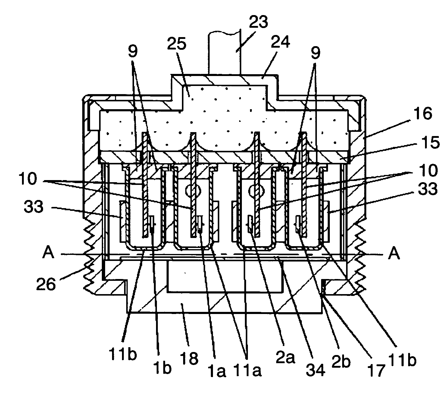
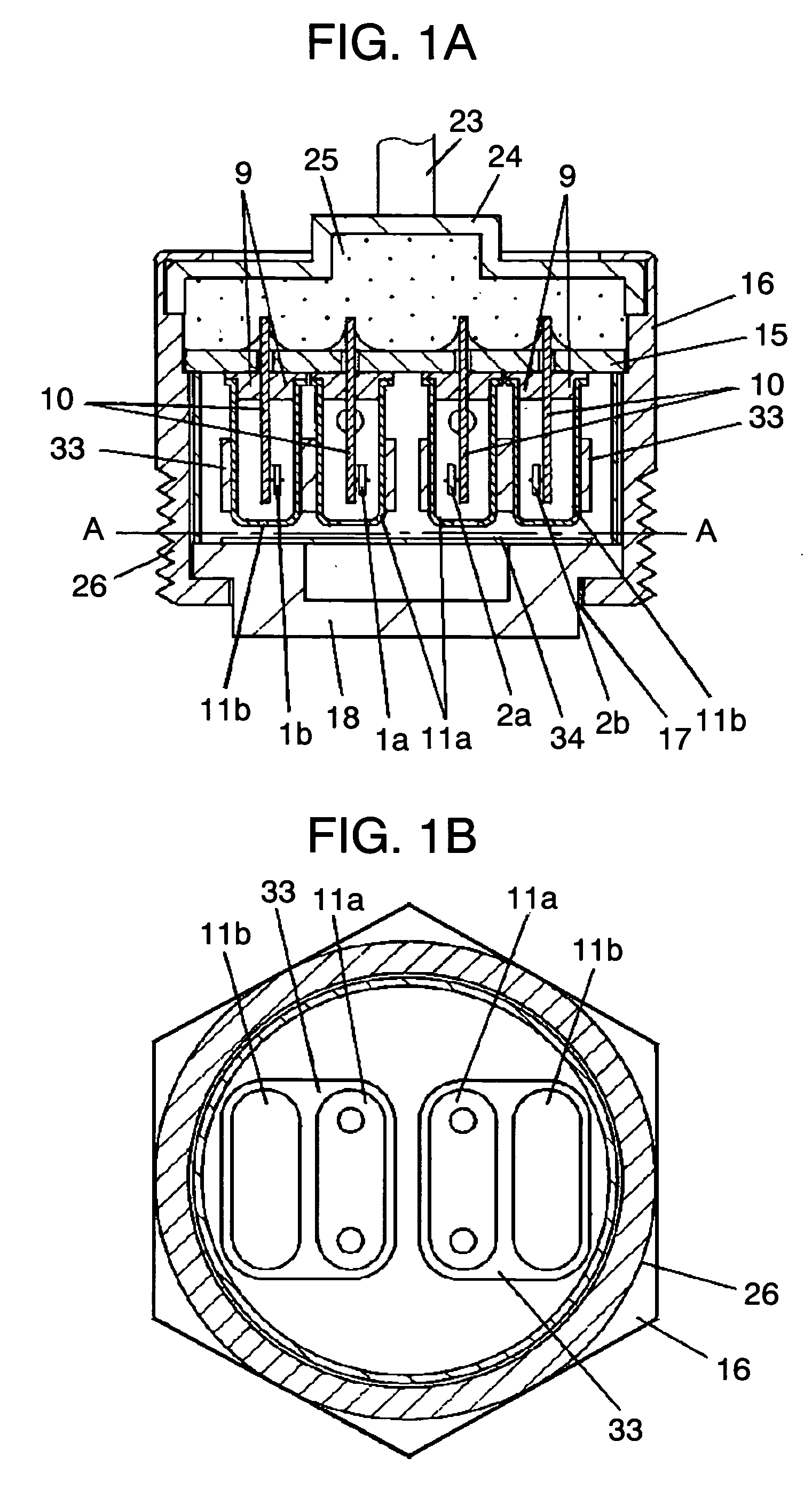
[0032]FIG. 1A shows GDH 1a, TDH 1b, GDL 2a and TDL 2b. Each of these elements is composed of a thermistor, of which a structure is shown in FIG. 2. Heat generating resistors of any kind can be used as these elements, if resistances are variable responsive to temperature change. Thermistor element 4 used here is made of a sintered oxide compound composed of manganese, cobalt, copper and vanadium, which is cut into a disc-like shape of 1.2 mm in diameter and 0.2 mm in thickness. B-constant defining a temperature characteristic of it is 2,300K. However, any element having a value in a range of approximately 1,000 to 3,000K may also be used. Thermistor element 4 is provided with electrodes 5 formed on both surfaces thereof by printing and firing conductive paste of silver, palladium and platinum based material. Lead wires 6 made of a platinum wire of 0.15 mm in diameter are connected electrically and mechanically to the both electrodes 5 with the condu...

second exemplary embodiment

[0084] (Second Exemplary Embodiment)

[0085] In the following second exemplary embodiment, like reference marks are used to designate like elements as those of the first exemplary embodiment, and description of them will be omitted.

[0086] A gas detector of this exemplary embodiment differs from that of the first exemplary embodiment in respects that DPH 35a comprises second TDH 1c, and DPL 35b comprises second TDL 2c, in addition to the structure of the first exemplary embodiment.

[0087] Description is provided in detail hereinafter. In FIG. 9A and FIG. 9B, second TDH 1c and second TDL 2c are each composed of a thermistor, like those of the first exemplary embodiment. FIG. 2 shows a structure.

[0088] The structures of second TDH 1c and second TDL 2c are analogous to the like elements described in the first exemplary embodiment. As shown in FIG. 9A and FIG. 9B, each of the sensor elements is enclosed in unperforated casing 11b in a space filled with dry air, and the unperforated casin...


PUM


Abstract

There is provided a gas detector capable of detecting hydrogen concentration and humidity independently in the environment containing both hydrogen and water vapor. The gas detector comprises a high-temp exothermic detector unit and a low-temp exothermic detector unit provided with themosensitive resistors of different self-heating temperatures. The gas detector converts gas-level outputs produced by the high-temp exothermic detector unit and the low-temp exothermic detector unit responsive to the hydrogen concentration and humidity into electric signals, and outputs them after computing electrically levels of the hydrogen concentration and humidity contained in a gas introduced into the two detector units through a gas intake opening.

Description

TECHNICAL FIELD [0001] The present invention relates to a gas detector for detecting hydrogen leakage and humidity. BACKGROUND ART [0002] There are intense activities in recent years for development of fuel cells that generate electric power from hydrogen and oxygen in the air. These activities are motivated by three reasons below. [0003] First, they are excellent power generating methods in view of the environmental protection, because substance being released during generation of electricity is only water. Secondly, they save energy because they are fundamentally superior in efficiency of generating the electric energy. Thirdly, they have an advantage of using even thermal energy by collecting heat produced during generation of electricity. They therefore hold expectation as the last resort to solve the energy and environmental problems in the global scale. [0004] Such fuel cell systems as discussed above are considered useful for application to home-use cogeneration systems as we...

Claims


Application Information

Patent Timeline
IPC IPC(8): B60H1/00B60H1/24G01N27/18G01N33/00H01M8/00H01M8/04
CPCG01N27/18Y02E60/50H01M8/04089G01N33/005
Inventor KATSUKI, NOBUHARUSHOJI, RIHITOTADA, MASAKIYUKAWA, JUNICHI
Owner PANASONIC CORP
Why Eureka
Try Eureka