Coupling circuit arrangement for data communication over power lines

a technology of data communication and coupling circuit, which is applied in the direction of transmission, transmission system, automatic controller, etc., can solve the problems of not being able to reduce the physical dimension and cost of the coupling transformer, and being considered potentially dangerous to life, and achieve the effect of effectively preventing high voltage surges or transients

Inactive Publication Date: 2005-03-31
AVAGO TECH INT SALES PTE LTD
View PDF5 Cites 242 Cited by
  • Summary
  • Abstract
  • Description
  • Claims
  • Application Information

AI Technical Summary

Benefits of technology

[0019] The invention permits a space-saving design of the coupling circuit, constitutes a reliable isolation, effectively preventing that high voltage surges or transients from the power line are coupled into low voltage circuitry. According to an embodiment of the invention, the transmit power supply does not have to be isolated so that a simple low-cost non-isolated offline power supply may be used. This is of particular advantage in systems where only small amounts of isolated power are available or in systems where the power communications facility is added at a later point in time.

Problems solved by technology

Additionally in many cases the power line is distributing voltages levels, which can be considered potentially dangerous to life.
In some instances this may be achieved by means of the system housing or mechanical construction, but in many cases this is not a practical solution because the user has to have direct electrical access to the low voltage circuitry.
These two factors together mean that the ability to reduce the physical dimensions and cost of the coupling transformer is limited.
Another problem with coupling low voltage circuitry onto the power line with a transformer is that high voltage surges or transients within the communication passband are directly coupled into the low voltage circuitry, potentially damaging not only the power line interface components but also interconnected circuitry.
This problem is reduced with the use of surge protection devices however still represents a potential risk to overall system robustness.
This configuration however cannot be used in the case of system microcontrollers, which implement the modulator / demodulator function internally.
Because the power line medium is intended primarily to transmit power it does not have ideal characteristics for transmitting or receiving modulated communication data, particularly in terms of line impedance and attenuation loss.
However, the integration of the line driver within the modulator / demodulator is impeded by the fact that the most suitable lowest cost IC technology for the modulator / demodulator function is not the most suitable for the voltage and power requirements of the line driver.
Consequently combining the modulator / demodulator on the same IC results in compromises either in the function of the modulator / demodulator or the line driver circuit.

Method used


Image

  • Coupling circuit arrangement for data communication over power lines
  • Coupling circuit arrangement for data communication over power lines
  • Coupling circuit arrangement for data communication over power lines

Examples


Embodiment Construction

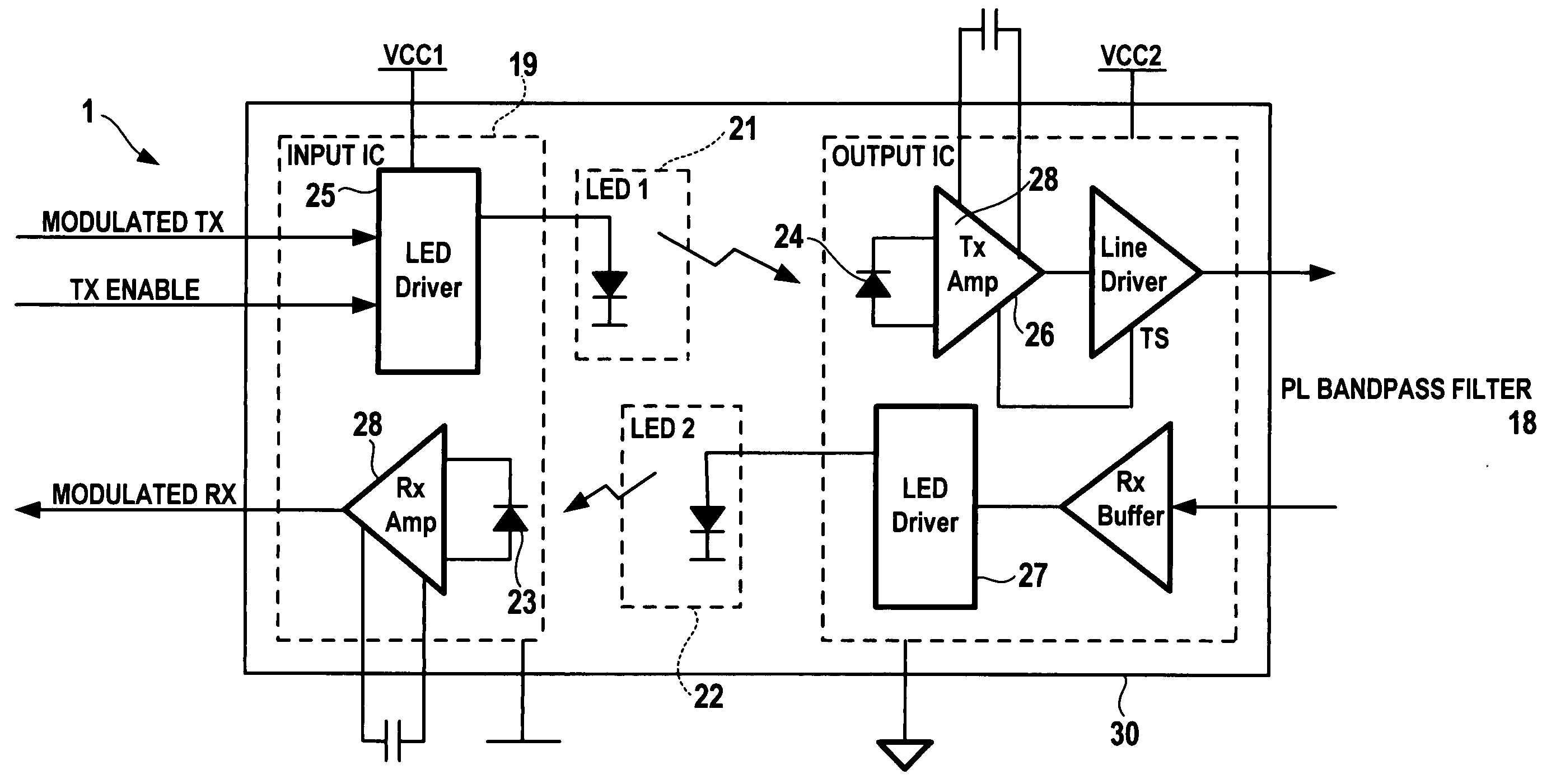
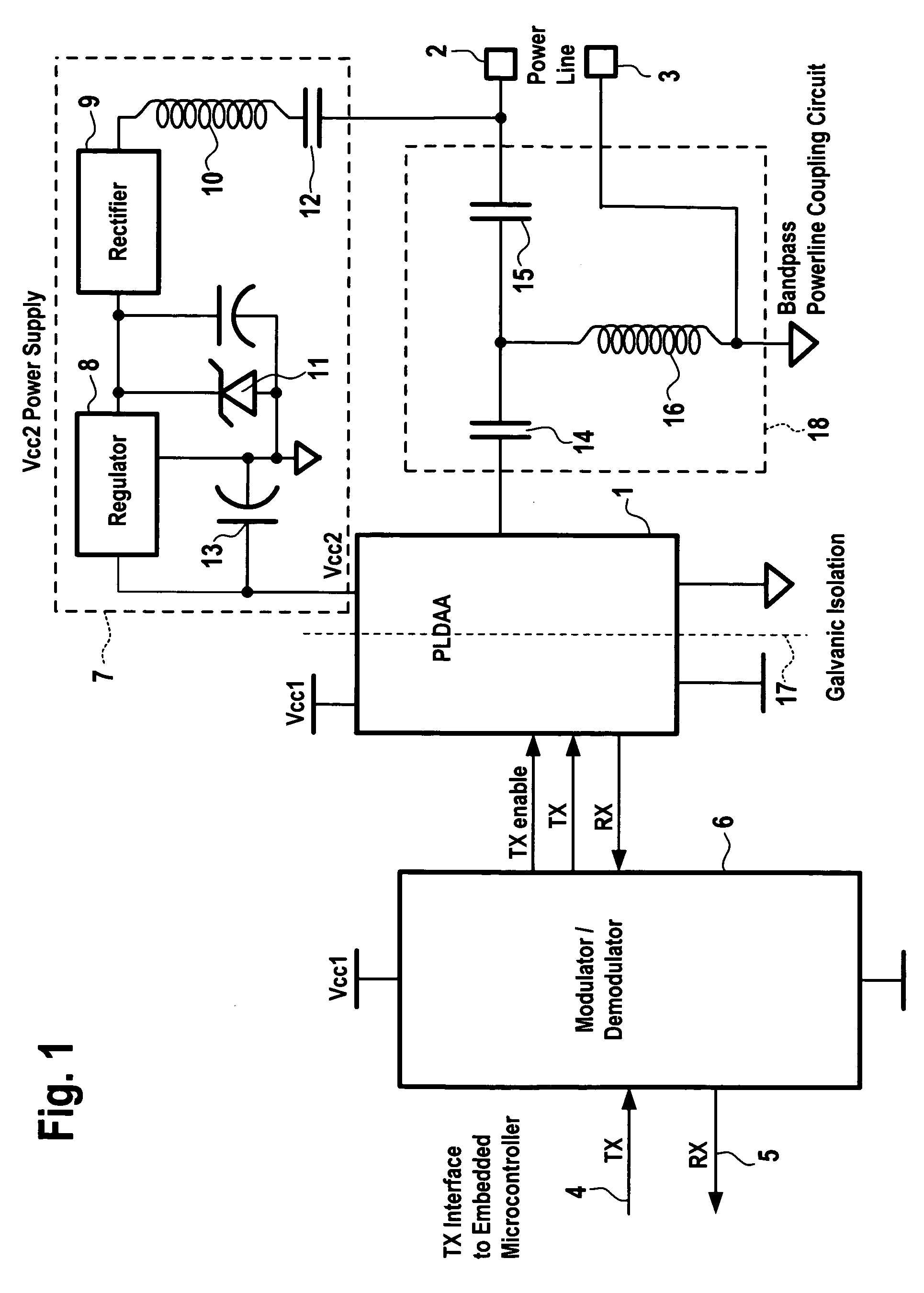
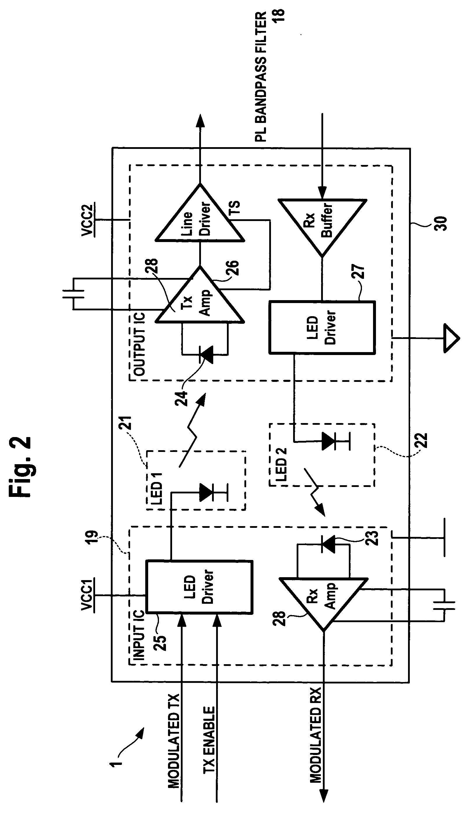
[0029] Referring to FIG. 1, the power line over which data are transmitted is indicated with terminals 2,3. The data which are to be coupled into the power line are supplied from external circuitry (not shown) on a transmit line 4 and the data which have been transmitted over the power line and which are to be supplied to subsequent data processing circuitry are supplied on a receive line 5. The letters TX in the drawings are used for “transmit” and the letters RX are used for “receive”. The direction of signal flow is indicated with arrows. The input TX signal on line 4 is supplied to a modulator / demodulator circuit 6, and the modulated output signal is supplied to a data access arrangement 1. The dotted line 17 in block 1 represents the galvanic isolation between the input and output circuitry. The data access arrangement 1 forms an important part of the invention and will be described in more detail below.

[0030] The data access arrangement 1 is connected to a power supply circui...


PUM


Abstract

A coupling circuit arrangement for data communication over a power line comprises a modulator/demodulator circuit for modulating data signals for transmission over the power line, and for demodulating signals which have been transmitted over the power line into data signals, a power supply circuit, and isolation means for providing galvanic isolation from the power line. The isolation means comprises light emitting elements and light detecting elements, which are arranged between the modulator/demodulator circuit and the power line. The isolation means may also be used to transmit a digital control signal which indicates the status of the power supply circuit or an over-temperature condition, or which is a transmit enable signal. The digital control signal may be encoded in the analog data signal by a digital shift in the DC bias level or by a complete removal of the DC biasing signal.

Description

[0001] The invention relates to a coupling circuit arrangement for data communication over power lines. Such a circuit arrangement is used to couple data to a power line for transmission over the power line and for receiving data may have been transmitted over the power line. BACKGROUND OF THE INVENTION [0002] Communications networks are commonly used to transport digital data between devices and systems in an industrial, residential or transportation environment. The digital data can contain encoded information such as voice, video, control or status information. To transmit and receive this data some kind of physical transmission medium is required. Examples are RF, Coax, Ethernet twisted pair, telephone cables and power line cables. [0003] In the prior art it has been suggested to use power lines to transmit and receive communication data. Examples are described in U.S. Pat. No. 5,241,283 and U.S. Pat. No. 5,452,344. The power line is a connectivity medium primarily used to trans...

Claims


Application Information

Patent Timeline
Patent Type & Authority Applications(United States)
IPC IPC(8): H04B3/56
CPCH04B3/56H04B2203/5491H04B2203/5483H04B2203/5458
Inventor SULLIVAN, PATRICK
Owner AVAGO TECH INT SALES PTE LTD
Why Eureka
Try Eureka