
Devices and methods for using centripetal acceleration to drive fluid movement in a microfluidics system

a microfluidics and fluid movement technology, applied in the direction of track following on disks, maintenance of head carriers, biomass after-treatment, etc., can solve the problems of increasing the complexity of instruments designed to use microchips, increasing the flexibility or usefulness of these machines, and difficulty in designing systems for moving fluids on microchips. achieve the effect of facilitating the movement of samples

Inactive Publication Date: 2005-03-31
TECAN TRADING AG TECAN GRP LTD
View PDF0 Cites 116 Cited by
  • Summary
  • Abstract
  • Description
  • Claims
  • Application Information

AI Technical Summary

Benefits of technology

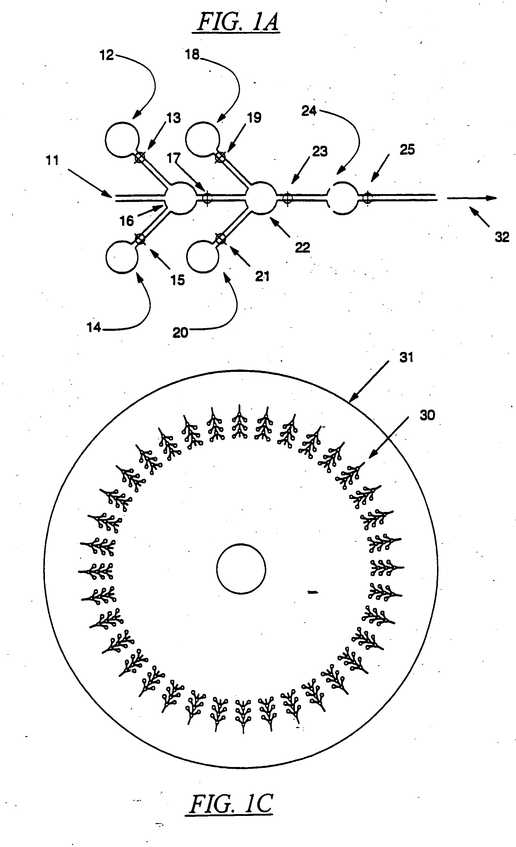
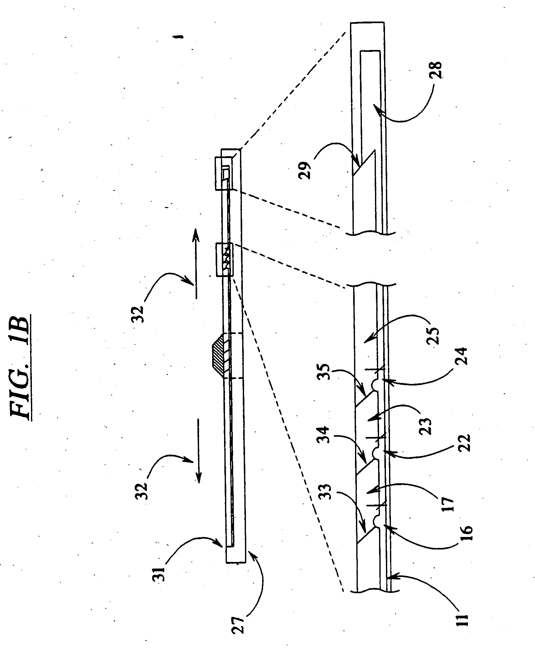
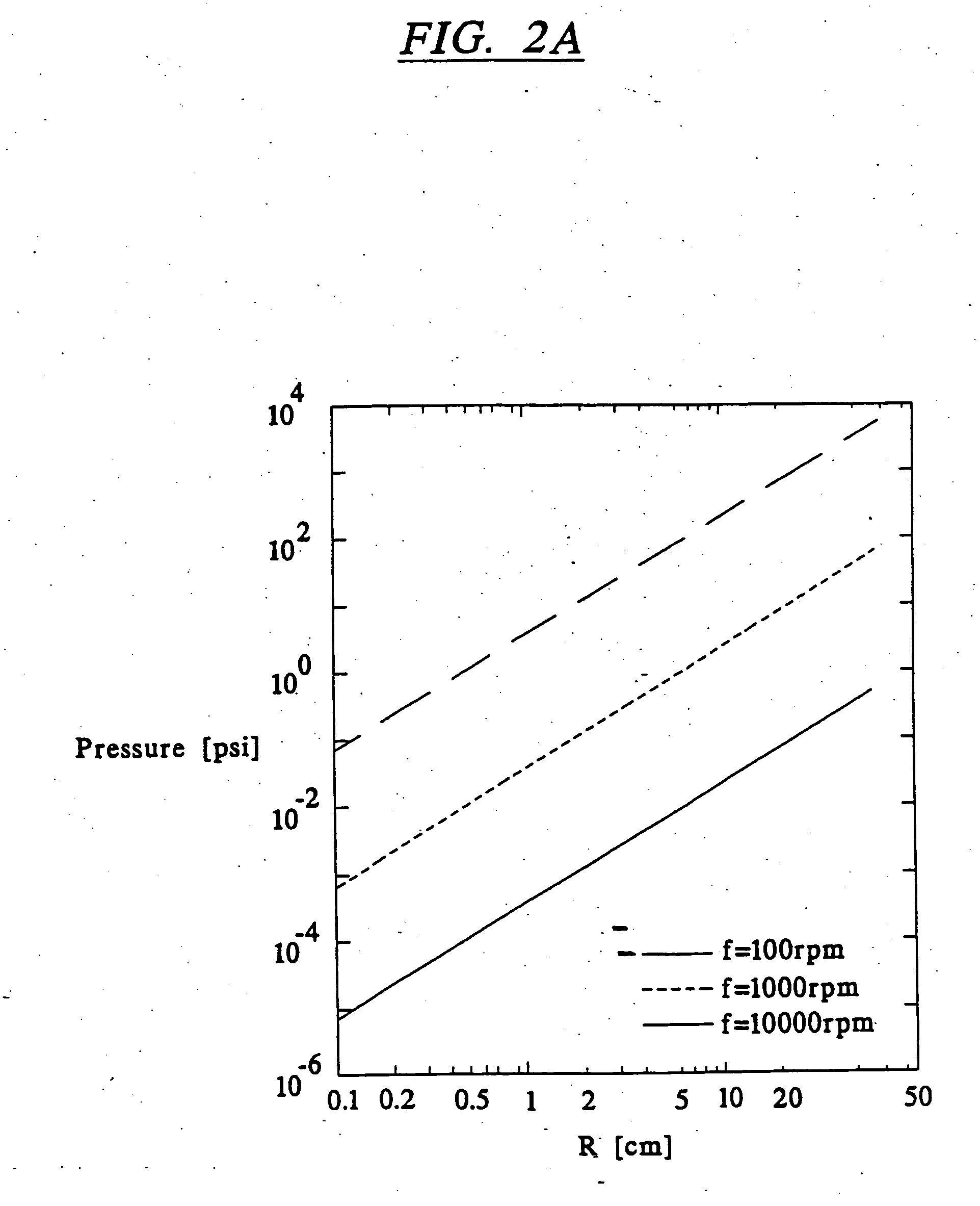
The invention provides methods and apparatus for the manipulation of samples consisting of fluids, cells and / or particles containing or comprising an analyte. The microplatform disks of the invention comprise Microsystems composed of, but no restricted to, sample input ports, microchannels, chambers, valves, heaters, chillers, electrophoretic and detection systems upon a disk. Movement of the sample is facilitated by the judicious incorporation of air holes and air displacement channels that allow air to be displaced but prevent fluid and / or particle loss upon acceleration.

Problems solved by technology

One drawback in the prior art microanalytical methods and apparati has been the difficulty in designing systems for moving fluids on the microchips through channels and reservoirs having diameters in the 10-100 μm range.
Also, the devices disclosed in the prior art have required separate data analysis and storage media to be integrated into an instrument for performing the microanalysis, thereby unnecessarily increasing the complexity of the instruments designed to use the microchips; without a concomitant increase in the flexibility or usefulness of these machines.

Method used


Image

  • Devices and methods for using centripetal acceleration to drive fluid movement in a microfluidics system
  • Devices and methods for using centripetal acceleration to drive fluid movement in a microfluidics system
  • Devices and methods for using centripetal acceleration to drive fluid movement in a microfluidics system

Examples


example 1

Fabrication of Microplatform Disks for Chemical Analysis, Synthesis, and Applications

Microplatform disks of the invention are fabricated from thermoplastics such as Teflon, polyethylene, polypropylene, methylmethacrylates and polycarbonates, among others, due to their ease of molding, stamping and milling. Alternatively, the disks can be made of silica, glass, quartz or inert metal. A fluid handling system is built by sequential application of one or more of these materials laid down in stepwise fashion onto the thermoplastic substrate. FIGS. 17A through 17E are a schematic representation of a disk adapted for performing DNA sequencing. Disks of the invention are fabricated with an injection molded, optically-clear base layer having optical pits in the manner of a conventional compact disk (CD). The disk is a round, polycarbonate disk 120 nm in diameter and 100 pm thick. The optical pits provide means for encoding instrument control programming, user interface information, graphic...

example2

Blood Composition Determination

Blood composition can be determined via hematocrit analysis using an analytic microplatform disk prepared as described in Example 1 held within a device comprising a microchannel layer with a number of microchannels as shown in FIG. 18. The microchannel layer is 100 pm thick and treated with heparin to prevent coagulation during the assay. The blood sample to be analyzed is drawn by capillary action into a channel arranged perpendicular to the direction of rotation, as shown in FIG. 18; a number of such channels may be arranged radially on the disk. When all samples to be tested have been drawn into the channels, the disk is spun at a speed of 8000 to 10,000 rpm to effect sedimentation of erythrocytes within the channel. Once centrifugation has been performed for an appropriate time (3 to 5 minutes), the hematocrit of each sample is determined simultaneously by stroboscopic interrogation of each of the channels using a conventional CD laser system in...

example 3

DNA Sizing and Mutation Detection

DNA sizing and detection of specific mutations in DNA at a particular site are carried out using double stranded melting analysis with a disk prepared according to Example 1 and illustrated in FIG. 20. A DNA meltometer (as described in co-owned and co-pending U.S. Ser. No. 08 / 218,030, filed Mar. 24, 1994 and incorporated herein by reference in its entirety) is advantageously incorporated into the structure of the disk Example 1. The DNA meltometer technique takes advantage of the fact that the denaturing point of a DNA duplex is dependent upon the length, the base composition, and the degree of complimentarity of the two strands in the duplex. A denaturing point may be determined in relation to some physical state of the molecule (such as temperature or the concentration of a denaturing chemical such as urea or formamide, and a set of standard conditions employed, the information derived from which can be stored in the microprocessor and / or memory ...


PUM

PropertyMeasurementUnit
Timeaaaaaaaaaa
Forceaaaaaaaaaa

Abstract

This invention relates to methods and apparatus for performing microanalytic and microsynthetic analyses and procedures. The invention provides a microsystem platform and a micromanipulation device for manipulating the platform that utilizes the centripetal force resulting from rotation of the platform to motivate fluid movement through microchannels. The microsystem, platforms of the invention are also optionally provided having system informatics and data acquisition, analysis and storage and retrieval informatics encoded on the surface of the disk opposite to the surface containing the fluidic components. Methods specific for the apparatus of the invention for performing any of a wide variety of microanalytical or microsynthetic processes are provided.

Description

BACKGROUND OF THE INVENTION 1. Field of the Invention This invention relates to methods and apparatus for performing microanalytic and microsynthetic analyses and procedures. In particular, the invention relates to microminiaturization of genetic, biochemical and chemical processes related to analysis, synthesis and purification. Specifically, the invention provides a microsystem platform and a micromanipulation device to manipulate the platform by rotation, thereby utilizing the centripetal forces resulting from rotation of the platform to motivate fluid movement through microchannels embedded in the microplatform. The microsystem platforms of the invention are also provided optionally having system informatics and data acquisition, analysis and storage and retrieval informatics encoded on the surface of the disk opposite to the surface containing the fluidic components. Methods for performing any of a wide variety of microanalytical or microsynthetic processes using the microsys...

Claims


Application Information

Patent Timeline
IPC IPC(8): B01F5/04B01F13/00B01J19/00B01L3/00B29C59/14F15C1/00F15C5/00F16K99/00G01N21/07G01N27/447G01N30/20G01N30/32G01N30/60G01N33/487G01N35/00
CPCB01L2300/0806Y10T436/111666B01L2300/0864B01L2300/0867B01L2300/087B01L2300/1827B01L2400/0406B01L2400/0409B01L2400/0421B01L2400/0622B01L2400/0633B01L2400/0655B01L2400/0661B01L2400/0688B29C59/14F15C1/005F16K99/0001F16K99/0013F16K99/0015F16K99/0017F16K99/003F16K99/0057F16K2099/0074F16K2099/0076F16K2099/008F16K2099/0082F16K2099/0084G01N21/07G01N27/44704G01N30/20G01N30/6095G01N35/00069G01N35/00732G01N35/00871G01N2030/326G01N2035/00782B01F5/0403B01F13/00B01F13/0059B01F15/0233B01F15/026B01F2215/0037B01J19/0093B01L3/5025B01L3/502707B01L3/502715B01L3/50273B01L3/502738B01L2200/027B01L2200/10B01L2300/0654Y10T436/11B01L2300/0861B01F25/31B01F33/00B01F33/30B01F35/71725B01F35/71805B01F2101/23
Inventor MIAN, ALECKIEFFER-HIGGINS, STEPHEN G.COREY, GEORGE C.
Owner TECAN TRADING AG TECAN GRP LTD
Learn More