Artificial heart power and control system

a control system and artificial heart technology, applied in the field of artificial heart power and control system, can solve the problems of prone to failure, complication in the removal of the device, and hindering the natural heart's ability to serve the function

Inactive Publication Date: 2005-03-31
EDER JEFFREY
View PDF2 Cites 185 Cited by
  • Summary
  • Abstract
  • Description
  • Claims
  • Application Information

AI Technical Summary

Benefits of technology

[0015] 8. It is a further object of the present invention to provide a rotatio

Problems solved by technology

This can cause several serious problems, including blood clots near the valve leaflets, which may break free to cause thromboemboli, or may become infected.
If the device captures all the flow for a prolonged period of time, even if no thrombi form, the natural valve leaflets may fuse together, complicating removal of the device if the natural heart recovers, or hindering the natural heart's ability to se

Method used


Image

  • Artificial heart power and control system
  • Artificial heart power and control system
  • Artificial heart power and control system

Examples


Embodiment Construction

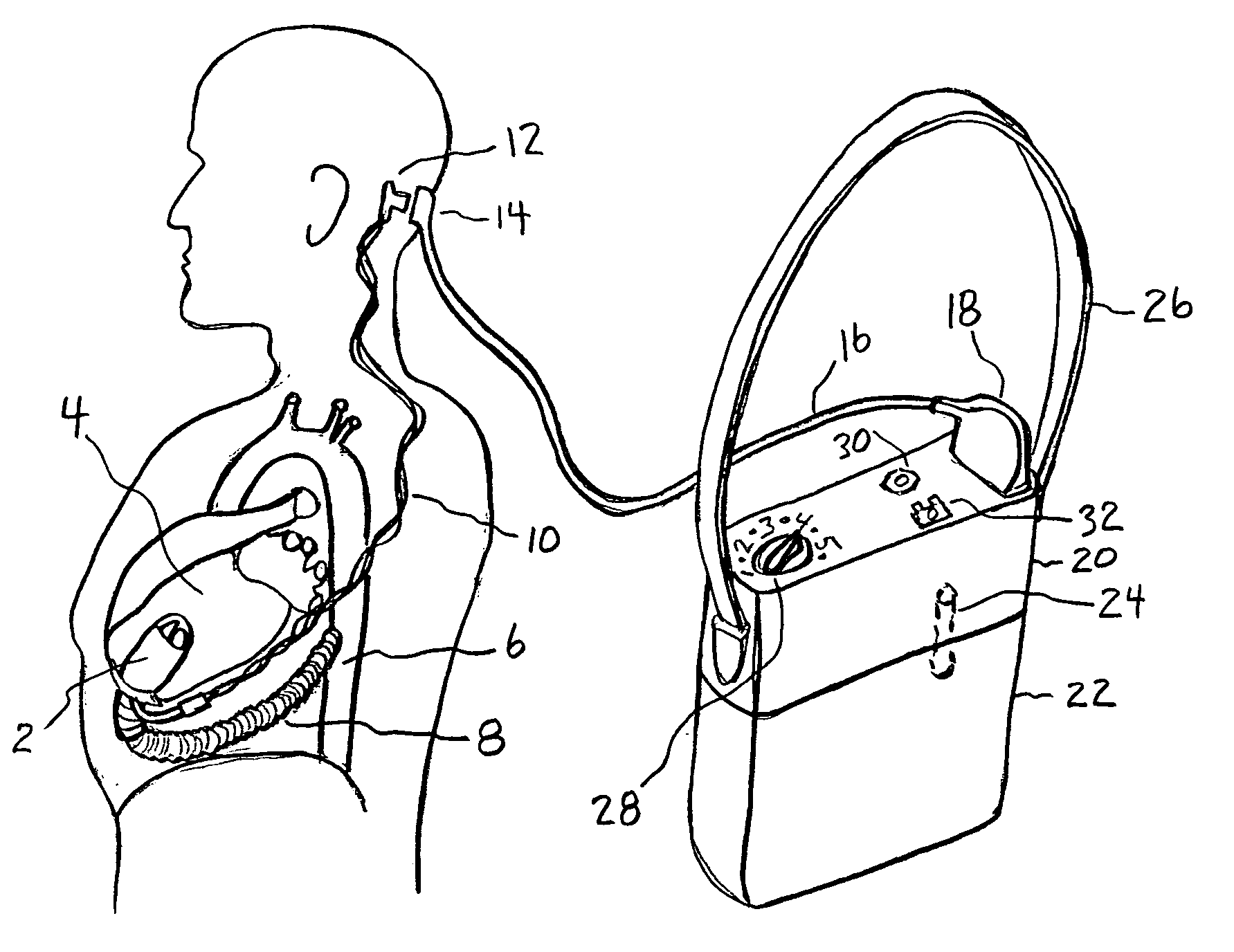
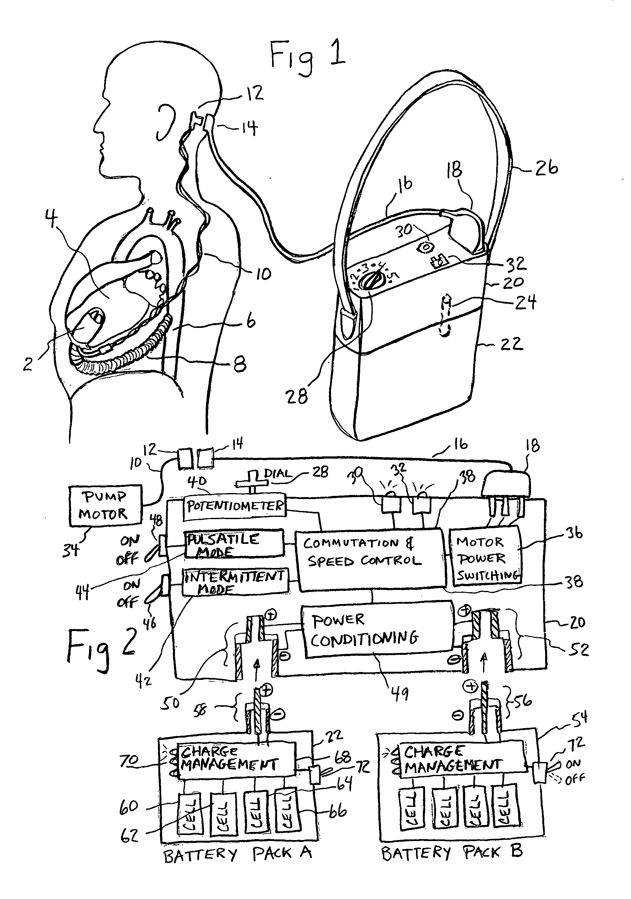
[0025]FIG. 1 illustrates the preferred embodiment of the invention. A rotary left heart assist axial flow blood pump 2 is implanted into the left ventricle 4 and connected to the aorta 6 by a vascular graft 8. A three phase electric motor which is contained within the blood pump 2 is powered via three wires of an implanted power cable 10. The cable crosses the skin at a percutaneous lead 12 which may include a connector 14 by which it is attached to an external power cable 16 having a plug 18 which permits the individual wires of the cable to be connected to the electronics control system 20. A battery pack which may contain multiple cells and will be referred to in this disclosure as simply a battery, is removably connected to the control system 20 by a coaxial connector 24, which is comprised of a receptacle—(FIG. 4) mounted directly within the control system and a plug—(FIG. 4) mounted within the battery. When mounted together as shown, the control system and battery form an inte...


PUM


Abstract

The present invention provides a human engineered power and control system for artificial hearts or assist devices configured for ease of use, ruggedness, and high reliability. Battery powered systems of the prior art have required multiple cables and connectors that are subject to failure due to damage or wear. In the present invention, direct connection of the batteries to the control system eliminates multiple cables and connectors used with previous designs. A novel method of connecting batteries to the control system and exchanging batteries without interruption of power is provided in a compact user friendly configuration. The control system may provide periodic reductions in assist device flow to permit the natural ventricle to eject blood through the natural outflow valve, open the valve leaflets to prevent them from adhering together, and achieve sufficient washout to prevent thrombosis. Using either software based control or software independent electronic circuitry, the flow pumped by the artificial heart is reduced for a long enough period of time to permit at least a few beats of the natural heart to generate sufficient pressure to open the outflow valve. In a control system embodiment in which the patient manually adjusts the pump speed to incremental settings for rest and exercise conditions, a pulsatile flow mode is disclosed which provides approximately the same flow at a given incremental setting as the pump produces when running in a constant speed mode at the same setting. As the patient learns which speed setting is best for daily activities, the patient may use the same setting with either a pulsatile or constant pump speed mode.

Description

BACKGROUND OF THE INVENTION [0001] Artificial hearts which support the right or left ventricles are blood pumping devices connected so that they receive blood from the atrium or ventricle, and pump it into the aorta (for a left heart assist device) or the pulmonary artery (for a right heart assist device). Electric rotary artificial hearts use axial flow pumps, centrifugal or mixed flow pumps powered by batteries to provide mobility and rehabilitate patients to a high quality of life. As patients resume a near normal life, the human engineering of the equipment they wear becomes an important aspect of their safety and comfort. External power and control systems must meet the physiologic needs of the patient to adjust the blood flow according to the level of exercise of the patient and other factors. Either the flow must be adjusted automatically using a computational algorithm, or it must be adjusted manually. [0002] If the device captures all of the flow entering the natural ventri...

Claims


Application Information

Patent Timeline
IPC IPC(8): A61M60/178A61M60/237A61M60/546A61M60/562A61M60/876H01M6/00H01M6/50
CPCA61M1/127H01M6/00A61M1/122A61M1/1005H01M6/50A61M2205/3334A61M60/562A61M60/148A61M60/546A61M60/237A61M60/178A61M60/876
Inventor JARVIK, ROBERT
Owner EDER JEFFREY
Why Eureka
Try Eureka