
Coating apparatus and processes for forming low oxide coatings

a coating apparatus and technology of low oxide coating, applied in the direction of machines/engines, manufacturing tools, turbines, etc., can solve the problems of bond coatings that tend to suffer oxidation, special metals are often required, and failure of tbcs

Active Publication Date: 2005-04-14
GENERAL ELECTRIC CO
View PDF15 Cites 10 Cited by
  • Summary
  • Abstract
  • Description
  • Claims
  • Application Information

AI Technical Summary

Benefits of technology

[0008] A process for welding a substrate and forming a low oxide bond coat during the welding process, the process comprising circumferentially maintaining an inert atmosphere about an area of the substrate to be welded, wherein maintaining the inert atmosphere comprises circumferentially vacuuming about the plasma arc with a local environmental cell; welding the substrate and forming a molten pool in the area of the substrate, wherein the molten pool has a trailing edge and a leading edge; and selectively depositing a powder at the trailing edge as the molten pool is solidifying or prior to solidifying in an amount effective to form a bond coat layer on t...

Problems solved by technology

When the application involves demanding operating conditions, specialty metals are often required.
The failure of a TBC is often attributed to weaknesses or defects related in some way to the bond coat, e.g., the microstructure of the bond coat or deficiencies at the bond coat-substrate interface or the bond coat-TBC interface.
One problem with current processes is that the bond coatings tend to suffer oxidation during normal thermal spraying in air.
However, the presence of oxides in the coatings detrimentally affect corrosion, strength and machinability.
Although various processes such as HVOF have been developed to improve other properties of the coating such as density and porosity among others, these processes are relatively expensive and by their very nature introduce oxygen into its plasma feedstream, thereby providing an inherent mechanism for oxide formation during coating.

Method used


Image

  • Coating apparatus and processes for forming low oxide coatings
  • Coating apparatus and processes for forming low oxide coatings
  • Coating apparatus and processes for forming low oxide coatings

Examples


Embodiment Construction

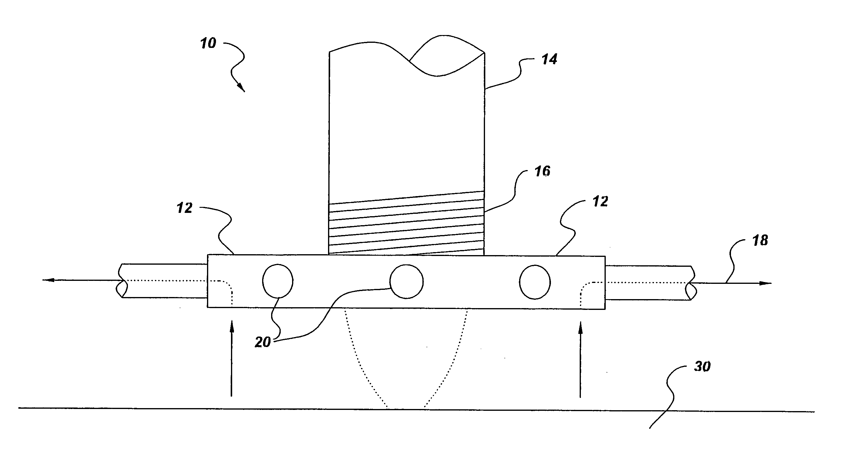
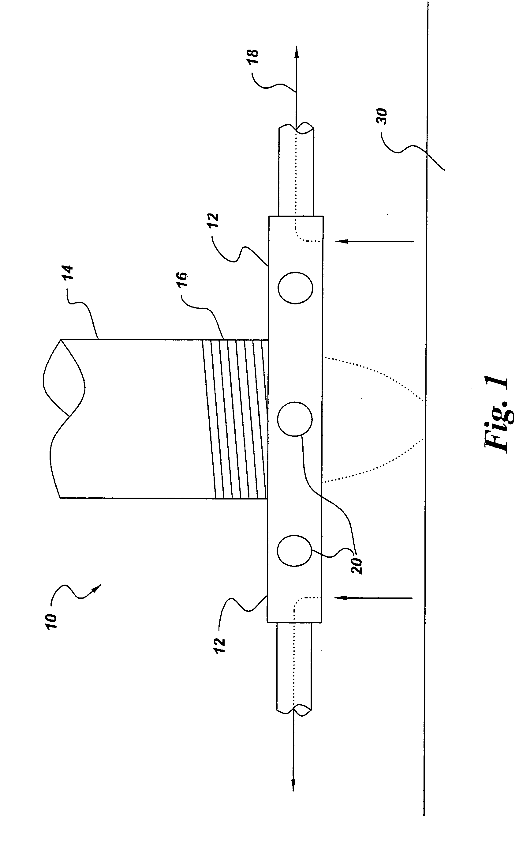
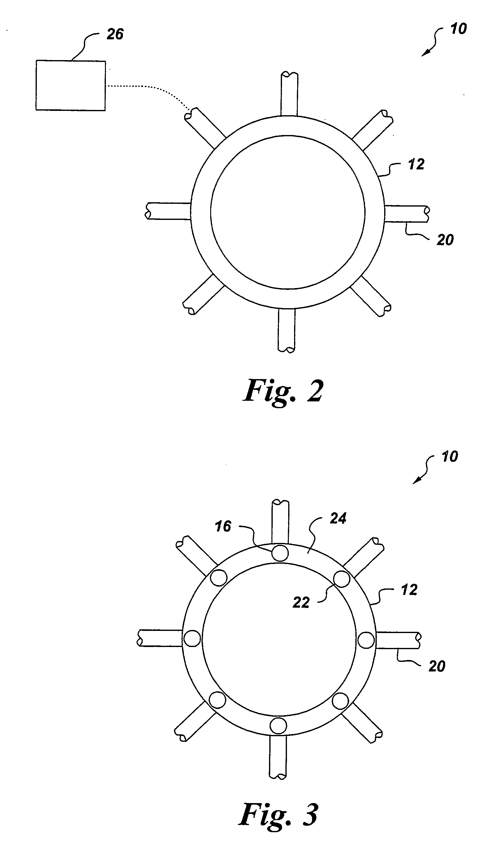
[0017] Referring now to FIGS. 1-3, there is shown a local environmental cell generally designated 10 for performing a welding operation such as a plasma transferred arc (PTA) or a gas tungsten arc (GTA) welding process in a controlled atmosphere. Welding processes such as the PTA and GTA welding processes generally flow an inert gas such as argon, helium and the like about a permanent tungsten electrode as is known in the art. The inert gas protects the electrode and generally shields the weld pool formed by exposing the substrate to the plasma. Advantageously and as will be discussed herein, the local environmental cell 10 eliminates the need for a separate spray cell for controlling the atmosphere about the welding spray gun and as such, increases the versatility of the welding operation. The local environmental cell circumferentially provides a uniform vacuum about the weld pool to remove contaminants from the substrate and provide an exhaust mechanism for ozone, non-reacted powd...


PUM

PropertyMeasurementUnit
Areaaaaaaaaaaa
Perimeteraaaaaaaaaa

Abstract

A local environmental cell for a welding spray gun includes an annular ring having a top surface and a bottom surface, wherein the annular ring is adapted for attachment to an outer perimeter of the spray gun; and a plurality of fluid passageways radially disposed about the annular ring comprising a plurality of openings in the bottom surface of the ring in fluid communication with a vacuum source for providing a vacuum thereto. The use of the local environmental cell permits deposition of local bond coats as well as minimizes the number of steps associated with welding repair processes. For example, the use of the local environmental cell permits welding and formation of a low oxide bond coat during the welding process, thereby eliminating the need for placing the substrate subsequent to a welding process in a separate spray cell to deposit the bond coating.

Description

BACKGROUND [0001] The present disclosure is generally related to welding and plasma spray processes and apparatuses such as may be desirable for fabrication, restoration or repair of metal articles. More particularly, the present disclosure relates to a welding process and an apparatus for producing low oxide bond coatings as well as a method for providing a bond coat during a welding process. [0002] Many types of metals are used in industrial applications. When the application involves demanding operating conditions, specialty metals are often required. As an example, components within gas turbine engines operate in a high-temperature environment. Many of these components are formed from nickel-base and cobalt-base superalloys. Since the components must withstand in-service temperatures in the range of about 1,100° C. to about 1,150° C., the superalloys are often coated with thermal barrier coating (TBC) systems. These coating systems usually include an underlying bond coat applied...

Claims


Application Information

Patent Timeline
IPC IPC(8): B05B7/22B05B12/16B05B14/00B05B15/00B05D1/10B23K9/04B23K10/00B23K10/02C23C4/02C23C4/12C23C4/134C23C4/137C23C6/00C23C26/02F01D5/28H05H1/42
CPCB23K9/04B23K9/044B23K10/00B23K10/027Y02T50/67C23C4/02C23C26/02F01D5/288B23K2201/001B23K2101/001Y02T50/60
Inventor FUSARO, ROBERT ANTHONY JR.SOLOMON, HARVEY DONALD
Owner GENERAL ELECTRIC CO
Learn More