
Metal-oxide-semiconductor device with enhanced source electrode

a technology of metal-oxide-semiconductor and source electrode, which is applied in the direction of semiconductor devices, basic electric elements, electrical appliances, etc., can solve the problems of not significantly increasing the cost of manufacturing ic devices, and achieve the effects of improving the high-frequency performance of the device, simplifying the process technology, and reducing the input capacitance of the mos devi

Active Publication Date: 2005-04-14
CICLON SEMICON DEVICE
View PDF16 Cites 11 Cited by
  • Summary
  • Abstract
  • Description
  • Claims
  • Application Information

AI Technical Summary

Benefits of technology

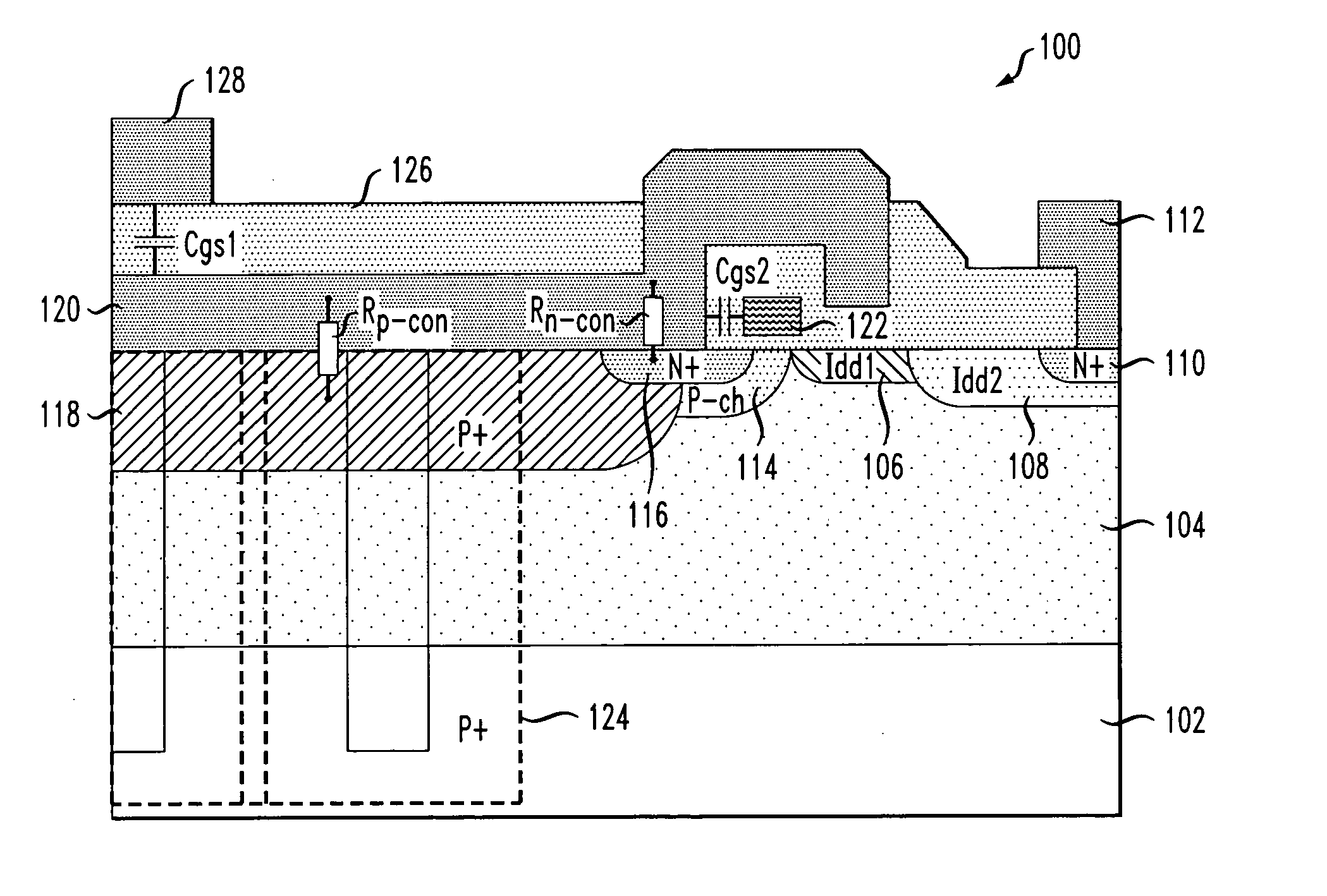
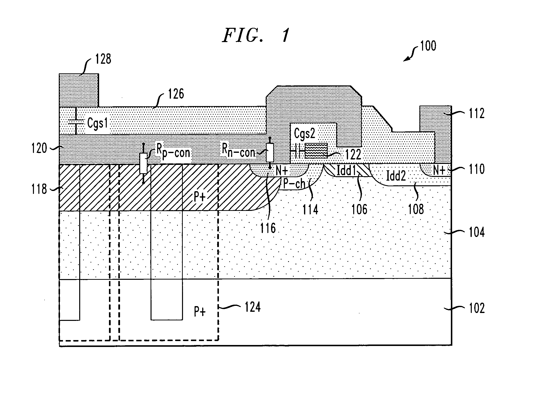
[0005] The present invention provides techniques for reducing an input capacitance of an MOS device without significantly impacting the source resistance of the device, thereby improving a high-frequency performance of the device. In an illustrative embodiment, when fabricating an LDMOS device, the techniques of the present invention advantageously eliminate the difficulties associated with using a dedicated metal layer to electrically connect an n+ region to a p+ region in a source region of the device, thereby significantly simplifying the process technology and improving device topology. Moreover, the techniques of the present invention can be used to fabricate an integrated circuit (IC) device, for example, an LDMOS device, using conventional CMOS-compatible process technology. Consequently, the cost of manufacturing the IC device is not significantly increased.
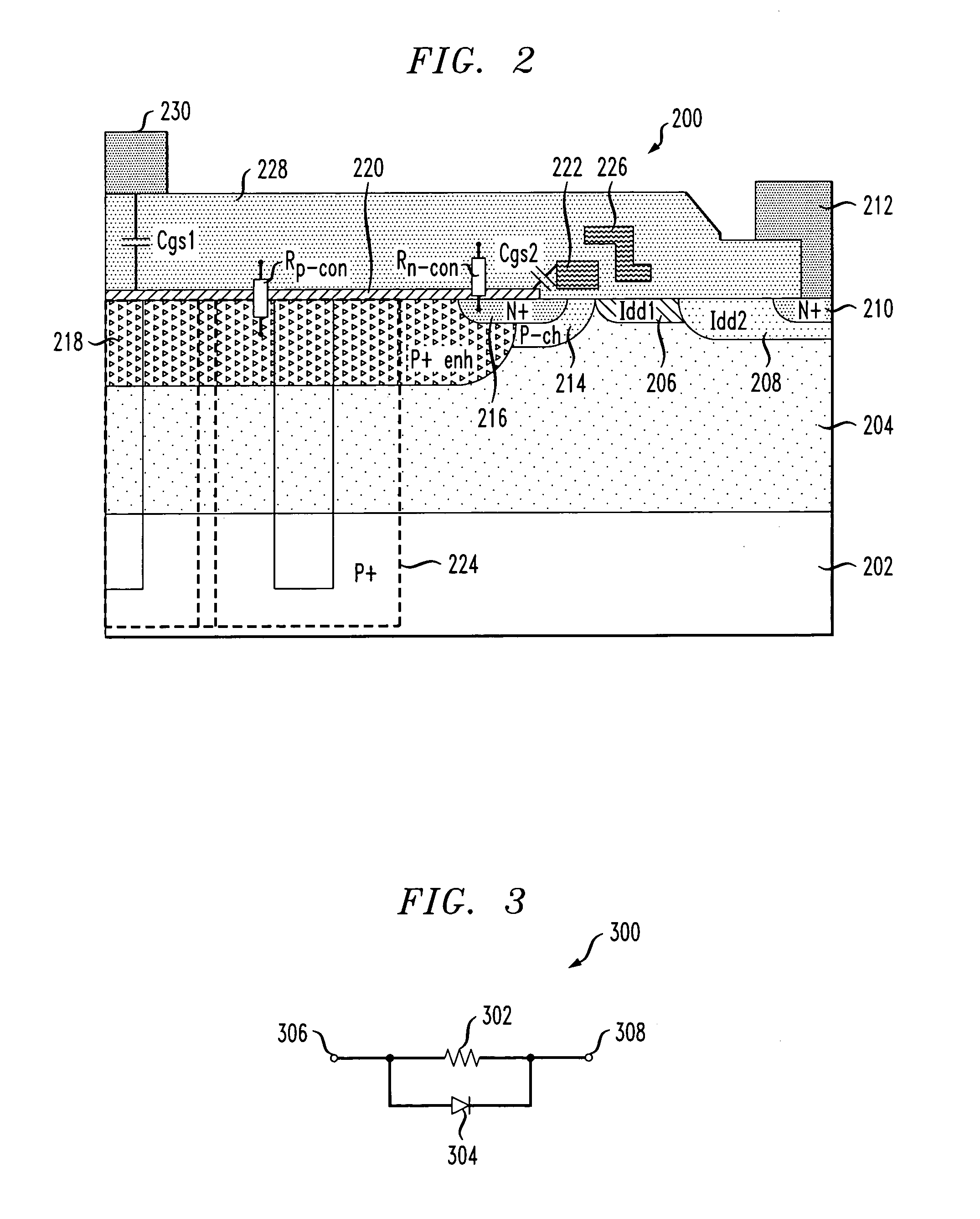
[0006] In accordance with one aspect of the invention, an MOS device is formed including a semiconductor layer of a first conductivity type, a source region of a second conductivity type formed in the semiconductor layer, and a drain region of the second conductivity type formed in the semiconductor layer and spaced apart from the source region. A gate is formed proximate an upper surface of the semiconductor layer and at least partially between the source and drain regions. The MOS device further includes at least one contact, the at least one contact including a silicide layer formed on and in electrical connection with at least a portion of the first source / drain region, the silicide layer extending laterally away from the gate. The contact further includes at least one insulating layer formed directly on the silicide layer. In this manner, the LDMOS device exhibits improved high-frequency performance, and is also substantially compatible with a CMOS process technology.

Problems solved by technology

Consequently, the cost of manufacturing the IC device is not significantly increased.

Method used


Image

  • Metal-oxide-semiconductor device with enhanced source electrode
  • Metal-oxide-semiconductor device with enhanced source electrode
  • Metal-oxide-semiconductor device with enhanced source electrode

Examples


Embodiment Construction

[0011] The present invention will be described herein in the context of an illustrative CMOS integrated circuit fabrication technology suitable for forming discrete RF LDMOS transistors, as well as other devices and / or circuits. It should be appreciated, however, that the present invention is not limited to the fabrication of this or any particular device or circuit. Rather, the invention is more generally applicable to an MOS device comprising a novel source electrode which advantageously enables the MOS device to provide improved high-frequency performance. Moreover, the device is fully compatible with a CMOS process technology. Although implementations of the present invention are described herein with specific reference to an LDMOS device, it is to be appreciated that the techniques of the present invention are similarly applicable to other devices, such as, but not limited to, a vertical diffused MOS (DMOS) device, an extended drain MOS device, etc., with or without modificatio...


PUM


Abstract

An MOS device is formed including a semiconductor layer of a first conductivity type, a first source / drain region of a second conductivity type formed in the semiconductor layer, and a second source / drain region of the second conductivity type formed in the semiconductor layer and spaced apart from the first source / drain region. A gate is formed proximate an upper surface of the semiconductor layer and at least partially between the first and second source / drain regions. The MOS device further includes at least one contact, the at least one contact including a silicide layer formed on and in electrical connection with at least a portion of the first source / drain region, the silicide layer extending laterally away from the gate. The contact further includes at least one insulating layer formed directly on the silicide layer.

Description

FIELD OF THE INVENTION [0001] The present invention relates generally to semiconductor devices, and more particularly relates to techniques for improving high-frequency performance in a metal-oxide-semiconductor (MOS) device. BACKGROUND OF THE INVENTION [0002] Power MOS devices, including laterally diffused metal-oxide-semiconductor (LDMOS) devices, are employed in a variety of applications, such as, for example, power amplifiers in wireless communications systems. A conventional LDMOS device utilizes a multiple-level metal fabrication process for forming an interconnection between regions of differing conductivity types (e.g., n-type and p-type) in a source region of the device. The source current is then generally routed via a low resistance p-type region to the back of the wafer, where a source contact is formed. [0003] In applications where high-frequency operation is desired, such as in a radio frequency (RF) range (e.g., above 1 gigahertz (GHz)), the conventional methodology f...

Claims


Application Information

Patent Timeline
Patent Type & Authority Applications(United States)
IPC IPC(8): H01L21/336H01L21/8234H01L29/08H01L29/417H01L29/45H01L29/76H01L29/78H01L29/94H01L31/062H01L31/113H01L31/119
CPCH01L29/0847H01L29/402H01L29/7835H01L29/456H01L29/4175
Inventor BAIOCCHI, FRANK A.JONES, BAILEY R.SHIBIB, MUHAMMED AYMANXU, SHUMING
Owner CICLON SEMICON DEVICE
Learn More