

Device for treatment of a gas flow
- Summary
- Abstract
- Description
- Claims
- Application Information
AI Technical Summary
Benefits of technology
Problems solved by technology
Method used
Image

Examples
second embodiment
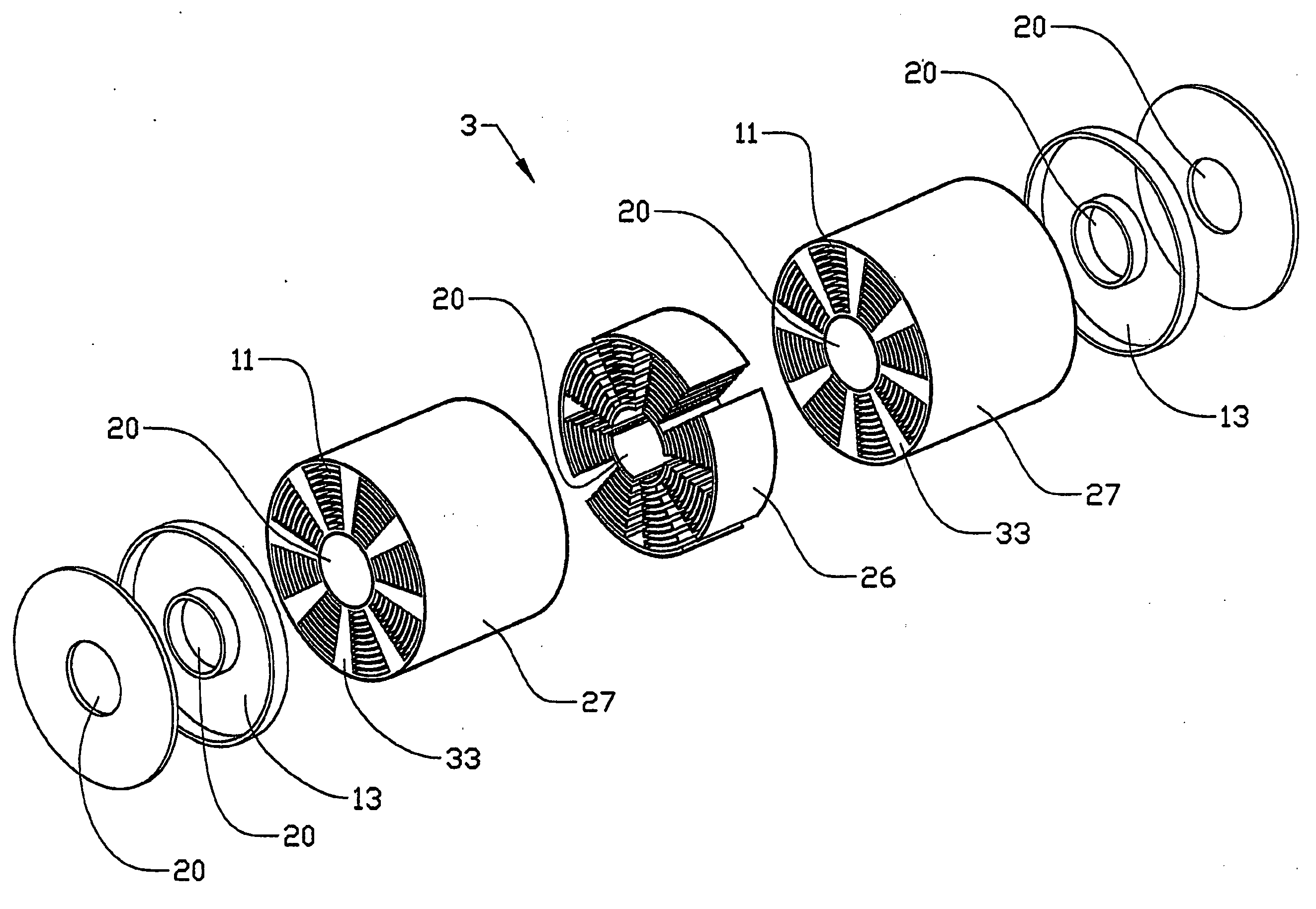
[0047]FIG. 4 shows a schematic sectional view of a variant of the second embodiment in which the body 3 constitutes two sub-bodies that have been joined together, and wherein each sub-body has a structure according to FIG. 3. The body 3 has also been provided with surrounding equipment for leading the gas to and from the body 3. FIGS. 5, 6, 7 and 8 shows sectional views A-A, B-B, C-C and D-D, respectively, according to FIG. 4. The structure of the distribution section 26 is not shown in FIG. 4, but in FIG. 5.
[0048] The incoming gas flow is fed into the body 3 through the first opening 4 into the internal cavity 20. The other end 23 of the cavity 20, opposite to that of the first opening 4, is closed, and which has the effect that the incoming gas flow is forced through the first openings 4′ of each distribution section 26. As can be seen in FIG. 5, the distribution section 26 constitutes of a wall structure forming (as an example) four first channels 29 that communicate with the int...
first embodiment
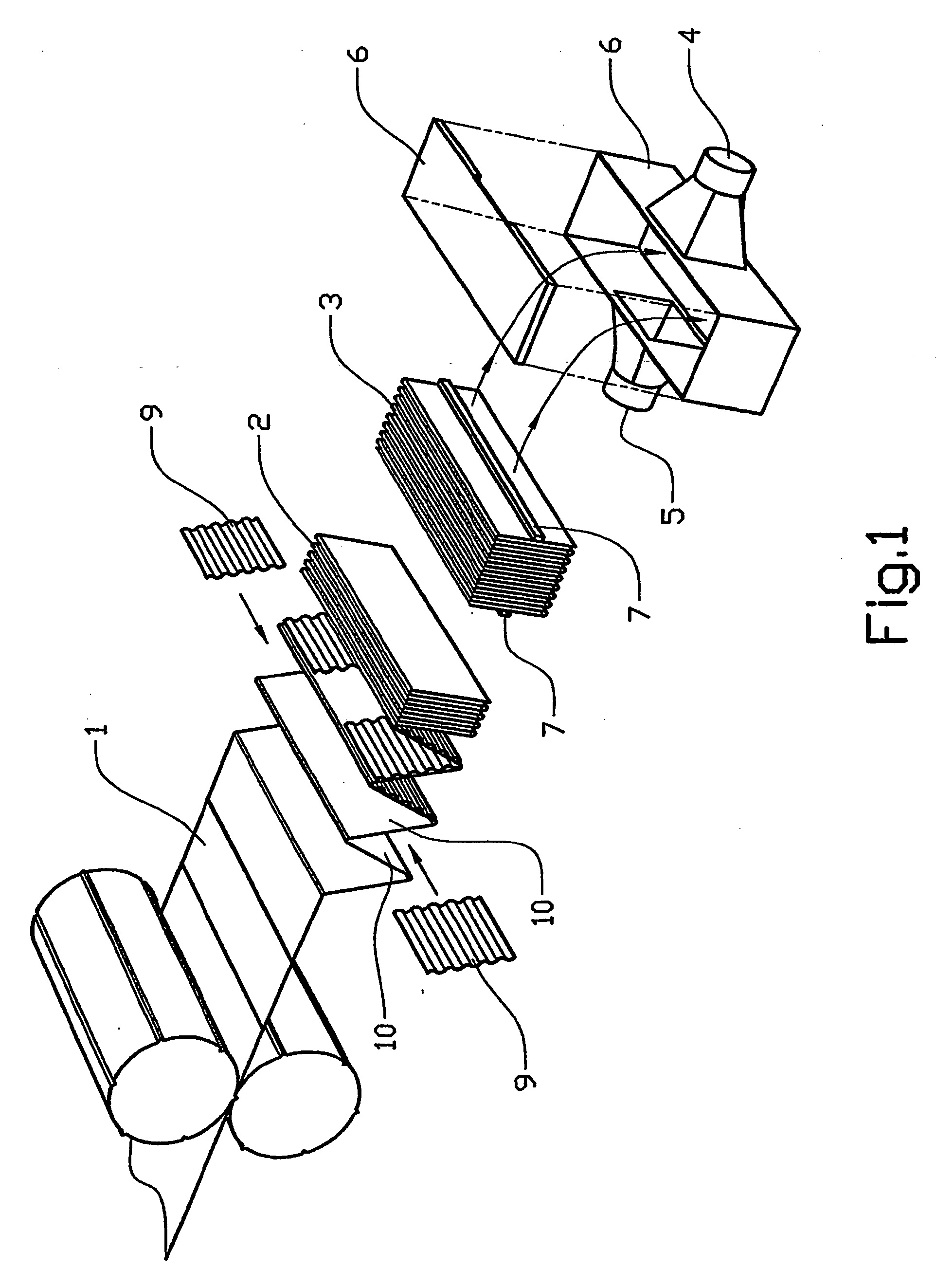
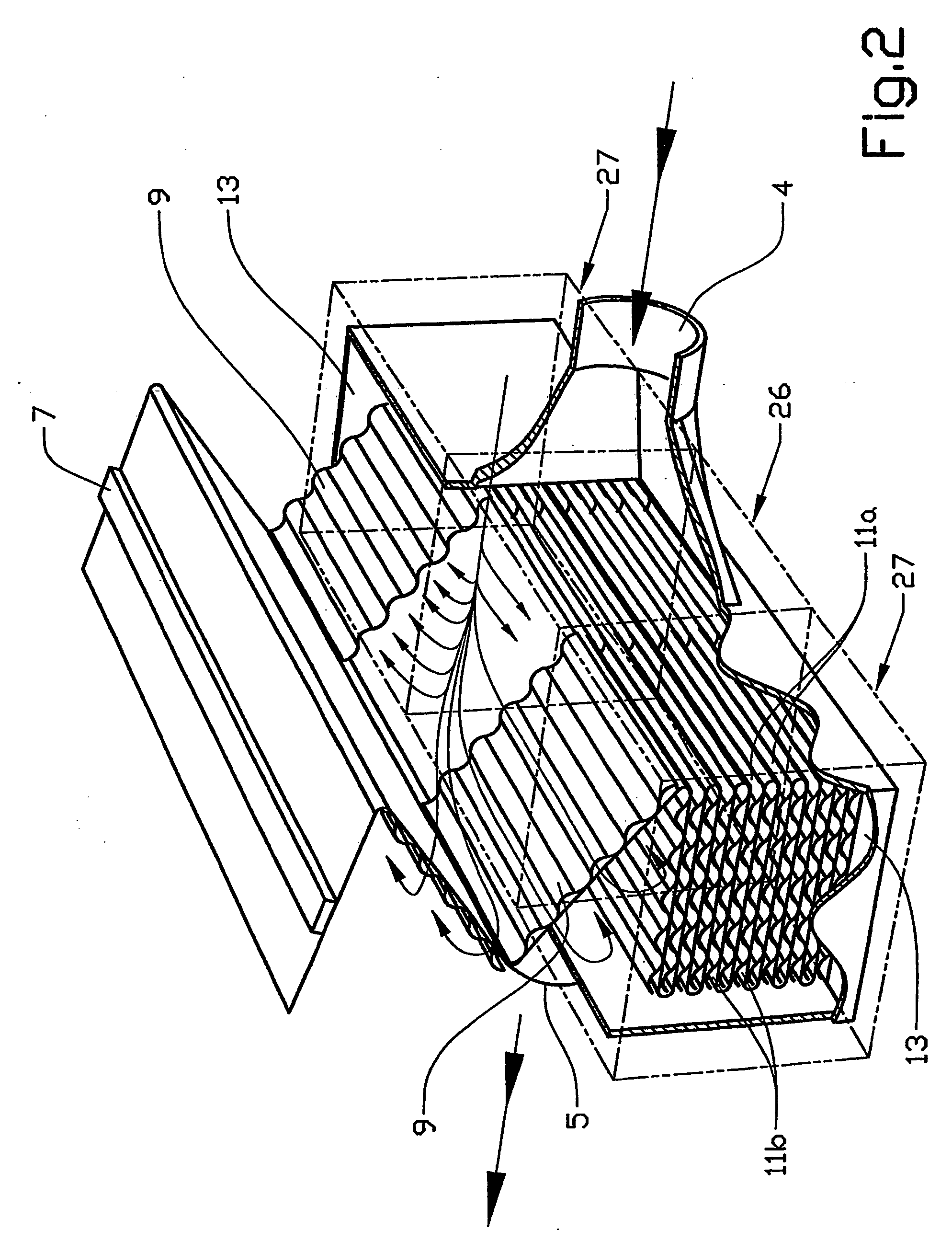
[0072] Further, the invention is not limited to the variant shown in FIGS. 1 and 2. The zigzag structure 2 can, for instance, be shaped to other geometrical structures. One example is to distribute the foldings 10 uniformly around an internal cavity so that the zigzag structure 2 takes the form of a circular cylinder with a longitudinal internal cavity. The gas can thus be fed to the body via the cavity. A variant of this is to form a discreet distribution of the foldings around the cavity wherein a number of sub-bodies are distributed around the cavity. The shape of the distribution section 26, i.e. the shape of the corrugated plates 9, may also be modified to suit different applications. Seen in the direction of the incoming gas flow, the distribution section 26 may for instance be narrowing or expanding.
[0073] Regarding the second embodiment of the invention, it is possible to use a conventional monolith with a large number of narrow flow passages (and provided with the internal ...
PUM
| Property | Measurement | Unit |
|---|---|---|
| Time | aaaaa | aaaaa |
| Composition | aaaaa | aaaaa |
| Flow rate | aaaaa | aaaaa |
Abstract
Description
Claims
Application Information