
Enhanced vapor containment and monitoring

a technology of vapor containment and monitoring, applied in the direction of liquid transfer devices, digital computer details, instruments, etc., can solve the problems of displacement loss, environmental hazard and negative impact on human health, and economic loss of retailers, so as to enhance the overall system, flexibility and vendor options

Inactive Publication Date: 2005-04-14
TIBERI TEDMUND P
View PDF6 Cites 17 Cited by
  • Summary
  • Abstract
  • Description
  • Claims
  • Application Information

AI Technical Summary

Benefits of technology

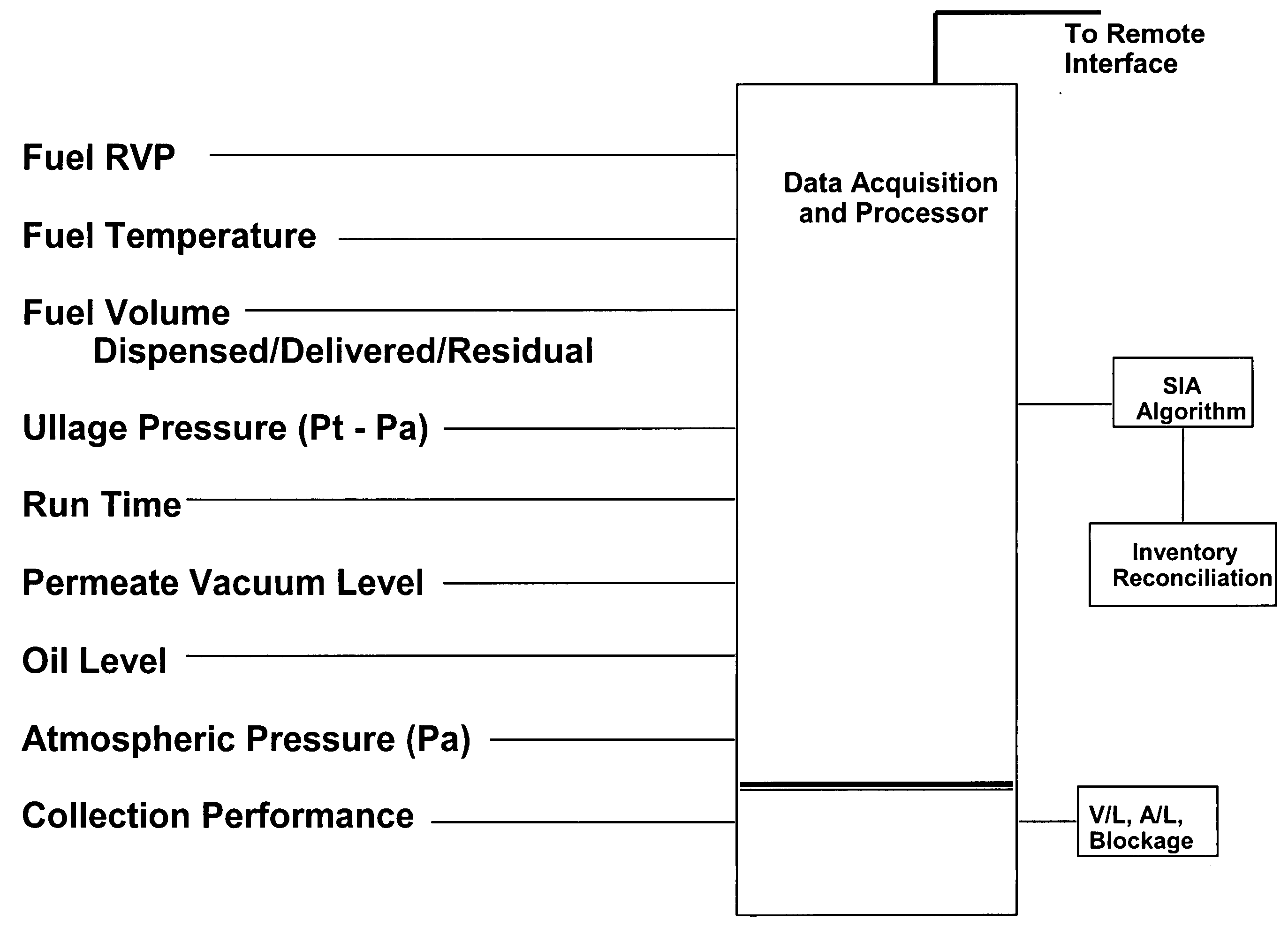
The inventory reconciliation is carried out by accessing volumetric data from a given refueling site by conducting reconciliation calculations on each individual storage tank employed at the site. This volumetric data includes gasoline dispensed, delivered, and opening and closing inventory levels in the each tank. Temperature variations are important since a 10 F change will result in a 0.7% change in gasoline volume. Without a common temperature basis, temperature variation can mask evaporative losses and / or liquid leaks. These data are obtained by presently existing hardware used in the dispenser, POS (point-of-sale) and ATG systems such as those provided by Incon (Franklin Fueling Systems), EBW (Franklin Fueling Systems), Emco Electronics (Dover Resources) and Veeder-Root (Danaher).
The combination of membrane based vapor processor hardware, a trend smoothed temperature compensated inventory reconciliation algorithm, tank, and line leak detection techniques will provide a continuous, on-going diagnostic of vapor recovery system performance as well as ensuring storage tank system integrity relative to vapor and liquid containment. As such, costly, cumbersome, inaccurate and maintenance intensive flow and concentration sensors are not required by petroleum marketers. A direct linkage is established between storage tank, interconnection piping leak detection, statistical inventory reconciliation, bulk tanker vapor recovery, vehicle vapor recovery system performance and storage tank vapor containment processor system performance. Each component is a key contributor to the overall integrated vapor recovery and containment at a given refueling site.
The integrity of the overall system is further enhanced by the use of a pressure monitor on the combined storage tank ullage and on the permeate vacuum pump. Also, cumulative run time of the vacuum pump motor is recorded. In addition to logging and reporting process conditions via various communication systems, such as via local or internet protocols, the system can be configured to automatically initiate predetermined safety measures such as shutting down dispenser pumps, sending emails or other types of alerts to service technicians, and actuating audible or visual alarms at the site. Such an approach leverages the value of presently required methods and enables the petroleum marketer to earn an economic return while at the same time taking steps favorable to the environment. Another commercial advantage earned by petroleum marketers is the flexibility and vendor options provided by such an approach.

Problems solved by technology

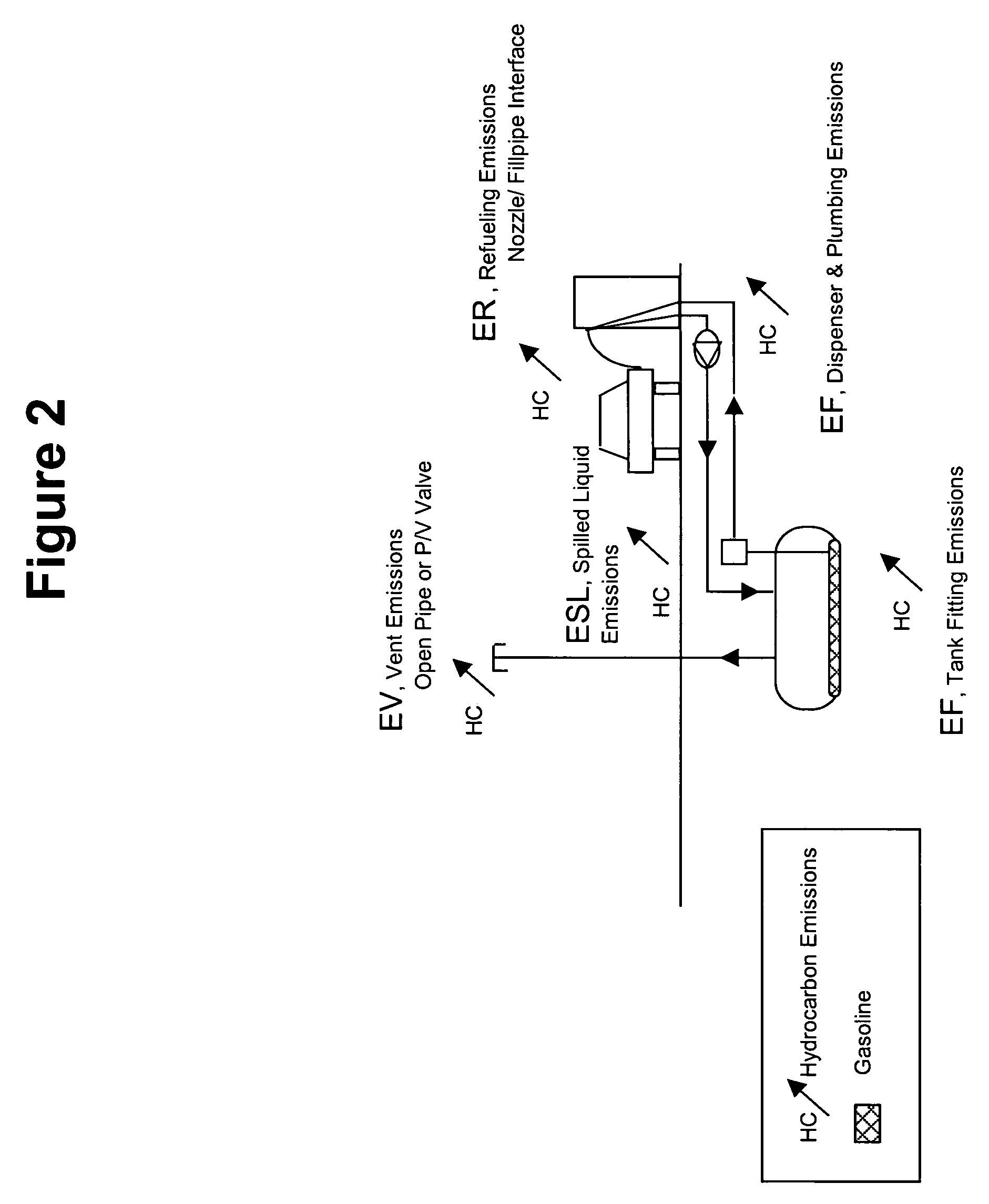
These gasoline vapor emissions represent an economic loss to the retailer, an environmental hazard and a negative impact on human health since benzene is a known human carcinogen.
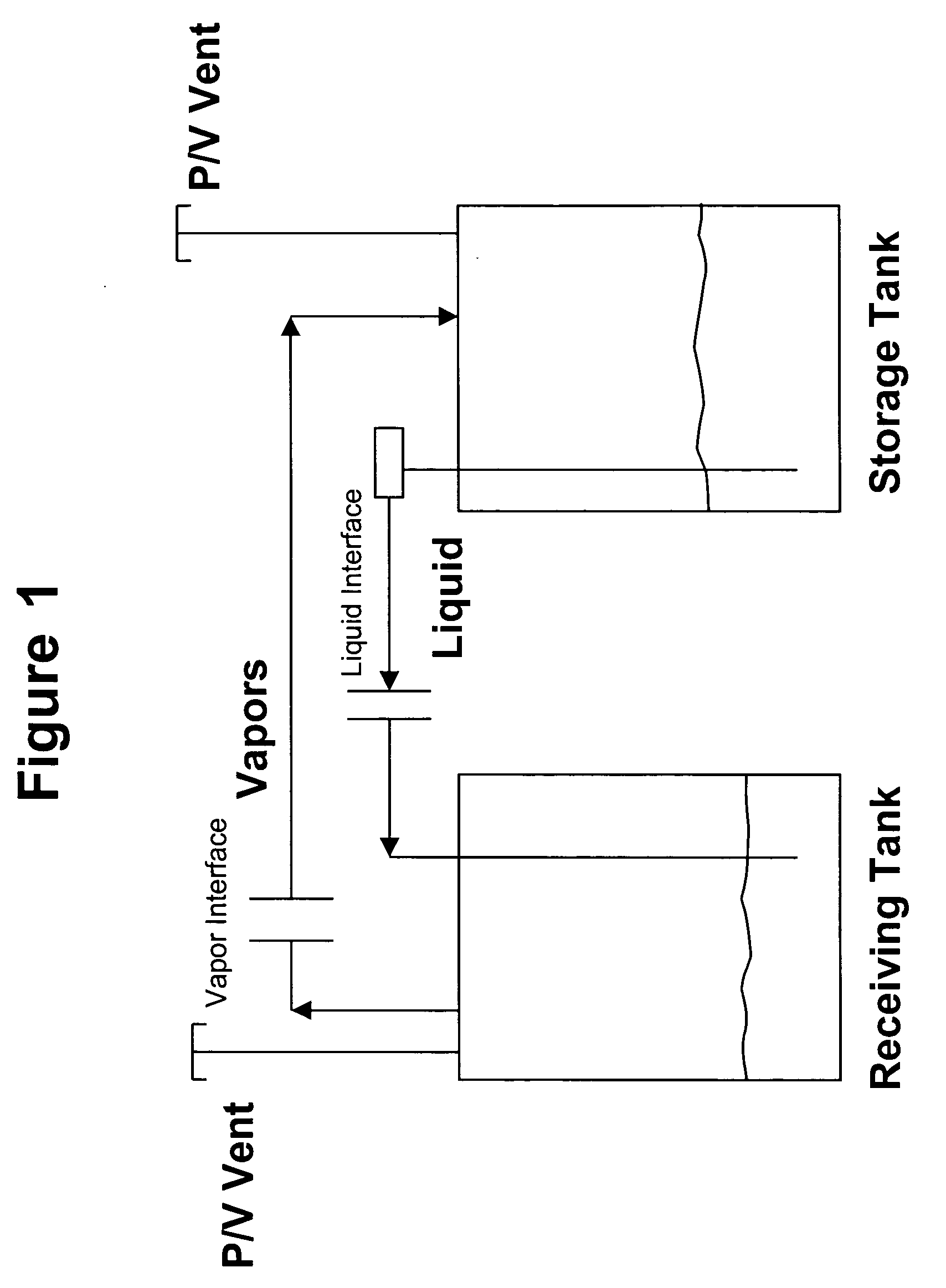
Accordingly, vapor losses from fixed-roof gasoline storage tanks includes displacement losses caused by inflow of liquid, breathing losses caused by temperature and atmospheric pressure variations, and emptying losses caused by evaporation of liquid after the transfer of product occurring during the interval between the next product delivery.
These losses include tank breathing losses caused by atmospheric pressure variations, wet-stock evaporative losses caused by air ingestion and excess vapor volumes developed during a bulk drop, even with Stage I vapor balance piping installed.
The relatively small figures of 1 pound of hydrocarbon evaporated for every 1,000 gallons of fuel dispensed have been recently challenged.
However, upon closer examination, the existing products and services suffer serious flaws.
If the owner or operator of a gasoline refueling station is confident that liquid leaks are not present, the other means of apparent or measured loss of mass are through evaporation loss, meter miscalibration, invoice errors, theft or volumetric changes due to temperature variation.
Without temperature compensation and isolation of inventory discrepancies, one can never be sure if inventory shortfalls or gains are the result of liquid leaks, meter inaccuracies, theft, product evaporation or invoicing errors from the wholesaler.
Also, time lag in measuring the data presents problems with correlating proper flow and HC concentration values (Mass=flow×HC Concentration).
(4) the “L” value is liquid flow rate determined by dispenser meters which are not temperature compensated, thus introducing a volumetric error even before associated HC masses are tabulated.
(5) The “A” or “V” values are volumetric flow rates of air or hydrocarbon / air mixtures which vary in both temperature and concentration, introducing additional measurement errors.
(6) Impact of ORVR equipped vehicles on returned flow rates is uncertain.

Method used


Image

  • Enhanced vapor containment and monitoring
  • Enhanced vapor containment and monitoring
  • Enhanced vapor containment and monitoring

Examples


Embodiment Construction

As seen in FIGS. 4-6, a refueling station storage tank system is equipped with a membrane system (1), a vacuum pump (2), an ATG console (3) and a data acquisition module (4). Two storage tanks (5) and (6) are shown. The selectively permeable membrane (1) was referenced previously and is shown connected to the combined vapor space or “ullage” of tanks (5) and (6). Tanks (5) and (6) are shown with their ullage spaces connected by conduit (7). (The figures show the tanks manifolded underground with individual vent lines; other piping combinations are contemplated as well). The combined ullage space is kept closed by the installation of p / v valves (8) and (9). In the United States, these valves have a typical setting of +3 inches water column and −8 inches water column. Such valves are commercially available from suppliers such as Husky, Hazlett Engineering and OPW Fueling Components. Also note in FIGS. 5 and 6 is a “front-end” vehicle vapor recovery system commonly known as a Stage II...


PUM


Abstract

An apparatus and method for ensuring effective and efficient vehicle vapor recovery performance, storage tank system integrity relative to both vapor and liquid containment and for reducing the probability that inaccurate information causes companies to undertake unnecessary, expensive and wasteful loss investigations at gasoline dispensing facilities. A fuel storage and delivery system is transformed from an “open system” communicating directly with the environment to a “closed system” which ensures capture, containment and accurate accounting of both hydrocarbon vapors and liquid phase product.

Description

TECHNICAL FIELD The present invention relates generally to the commercial distribution and sales of volatile motor fuels and more specifically to systems and methods for increasing overall vapor recovery efficiency and ensuring storage tank integrity at such volatile motor fuel dispensing facilities. BACKGROUND OF THE INVENTION Various stationary and mobile tanks are used in the production, storage and distribution of volatile organic compounds such as fuels, solvents and chemical feedstocks. When transferring a volatile fuel such as gasoline from a fixed roof storage tank to a fixed roof receiving tank, two events simultaneously occur. Vapors in the receiving tank ullage (space above the liquid) are displaced by the incoming liquid, and a negative pressure in the storage tank is developed in response to the dropping liquid level. The negative pressure in the storage tank is offset by either the ingestion of atmospheric air, or in the case of facilities equipped with Stage II vapo...

Claims


Application Information

Patent Timeline
IPC IPC(8): B67D7/04
CPCB67D7/0496B67D7/0486
Inventor TIBERI, TEDMUND P.
Owner TIBERI TEDMUND P
Learn More