
Circuit for controlling a fusing system

Inactive Publication Date: 2005-04-21
HEWLETT PACKARD DEV CO LP
View PDF14 Cites 19 Cited by
  • Summary
  • Abstract
  • Description
  • Claims
  • Application Information

AI Technical Summary

Benefits of technology

[0067] The circuit arrangements which have been disclosed achieve the desired goal of attenuated flicker. They are backward compatible with engine controllers and the Integral Half Cycle (IHC), phase control, or hysteresis control that the engine controllers utilize to control the power delivered to the fusing system. Circuits are disclosed which limit the maximum duty cycle of the IHC controller and provides a universal fusing system which can be used with any 50-60 Hz 90-240 VAC low voltage public power distribution system. The embodiments produce good power quality over the entire range of fuser power from 10-1000 watts, producing no harmonic currents and minimal sub-harmonics currents.

Problems solved by technology

These types of printers or copiers, however, tend to suffer from phenomenon know as “flicker.” Flicker is measured by the proposed European regulatory document IEC 61000-3-3, and is the impression of unsteadiness of visual sensation induced by a light stimulus whose luminance or spectral distribution fluctuates with time.
In electrical power distribution systems, flicker is the result of large current changes reacting with the power distribution system impedance causing voltage fluctuations.
These voltage fluctuations, in the form of voltage sags and surges, cause the light output of incandescent lamps to fluctuate and can cause fluorescent lamps to drop out.
Light flicker is visually irritating and also represents unwanted harmonics and power transients being placed on a power system.

Method used


Image

  • Circuit for controlling a fusing system
  • Circuit for controlling a fusing system
  • Circuit for controlling a fusing system

Examples


Embodiment Construction

[0029] For a dry electrophotographic fusing system to operate worldwide it must be able to operate satisfactorily on AC power systems providing from 90 Vrms to 240 Vrms at frequencies of 50 Hz to 60 Hz. The fusing system must heat up from ambient room temperature to operating temperature as quickly as possible while exhibiting extremely low flicker as its power consumption level changes. The fusing system, when combined with the balance of the electro-photographic printer power electronics, must meet International Electrical Commission (IEC) regulations IEC 61000-3-2 and IEC 61000-3-3 for current harmonics and flicker. The printer must pass Federal Communications Commission (FCC) class B regulations for power line conducted emissions and radiated emissions.

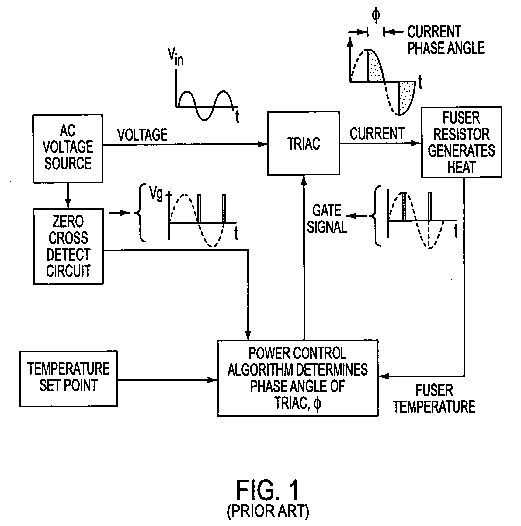
[0030] As noted above, fusers in many printers / copiers in use today employ what shall be referred to generically as a “triac control”. That is to say, the fusing systems are supplied with alternating current through a power switc...


PUM


Abstract

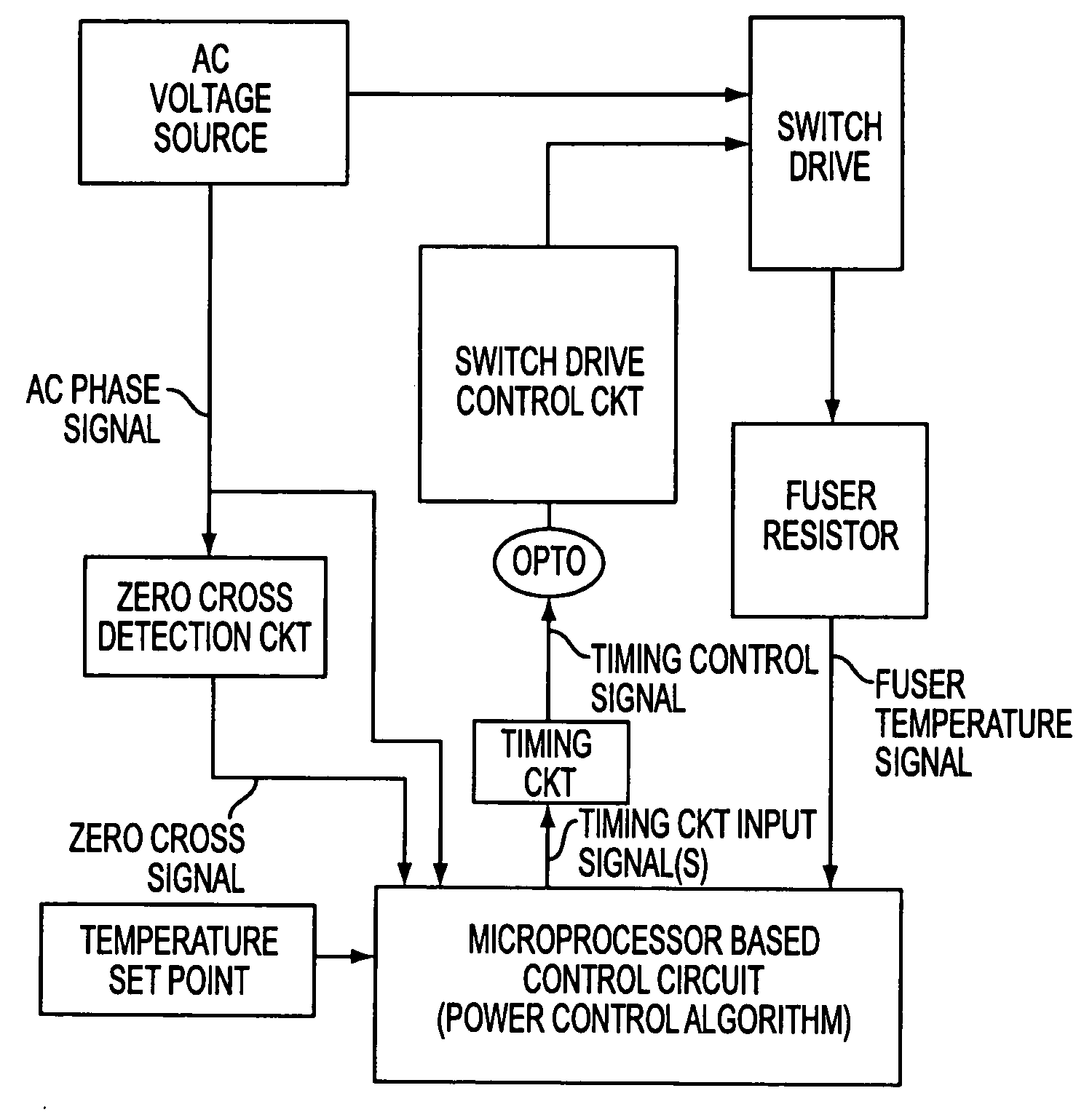
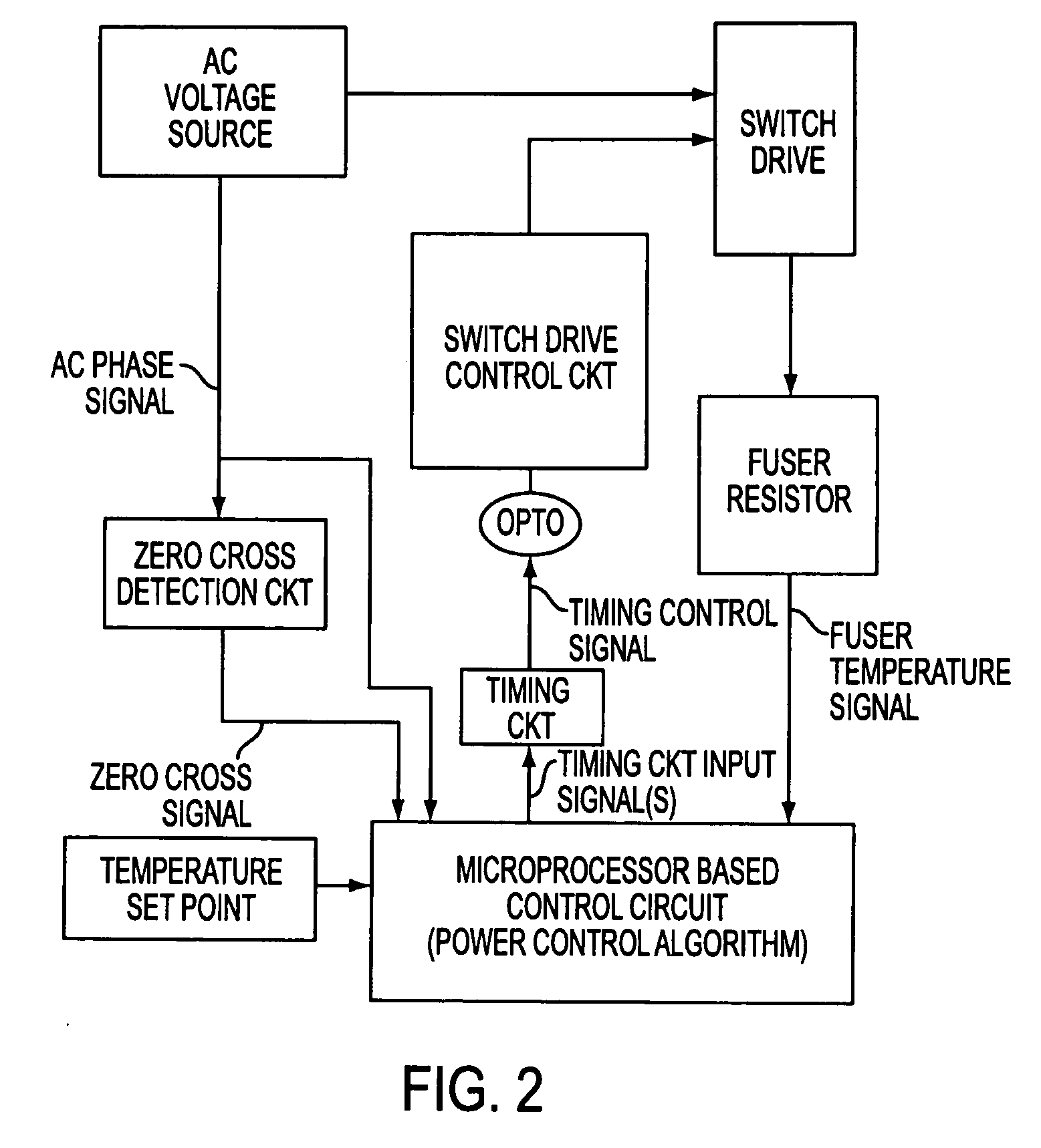
In an embodiment of the invention, a circuit for controlling a fusing system such as used in a printer, copier or the like, comprises a timing circuit; an averaging circuit which receives an output from the timing circuit and averages the signal to produce a voltage signal; a modulation circuit arrangement which receives the voltage signal from the averaging circuit and generates a train of pulses which varies with the voltage signal from the averaging circuit; and a switch driver circuit which is responsive to the pulse train from the modulation circuit and which drives a power supply switching circuit with a timing to apply a smoothly changing alternating current to the fusing system. The modulation circuit may be of the pulse width modulation type or the frequency modulation type.

Description

BACKGROUND OF THE INVENTION [0001] Dry electrophotographic copiers and printers develop an image utilizing a dry toner. The typical toner is composed of styrene acrylic resin, a pigment-typically carbon black, and a charge control dye to endow the toner with the desired tribocharging properties for developing a latent electrostatic image. Styrene acrylic resin is a thermo-plastic which can be melted and fused to the desired medium, typically paper. [0002] The typical fusing system in an electrophotographic printer or copier is composed of two heated platen rollers which, when print media with a developed image pass between them, melt the toner and through pressure physically fuse the molten thermal plastic to the medium. Heating is usually accomplished by placing one or more high power tungsten filament quartz lamps inside the hollow platen roller. [0003] These types of printers or copiers, however, tend to suffer from phenomenon know as “flicker.” Flicker is measured by the propose...

Claims


Application Information

Patent Timeline
IPC IPC(8): G03G15/20H05B1/02H05B3/02
CPCG03G15/80G03G15/2039
Inventor HIRST, MARK
Owner HEWLETT PACKARD DEV CO LP
Learn More