
Method and fine-control collimator for accurate collimation and precise parallel alignment of scanned ion beams

a collimator and parallel alignment technology, applied in the field of parallel ribbon-shaped chargedparticle beam production, can solve the problems of significant variations in the alignment of buried dopants, inability to optimize individual parameters of beam parallelism and current uniformity in general, and achieve the effect of fine control and more accura

Inactive Publication Date: 2005-04-21
WHITE NICHOLAS R
View PDF4 Cites 56 Cited by
  • Summary
  • Abstract
  • Description
  • Claims
  • Application Information

AI Technical Summary

Benefits of technology

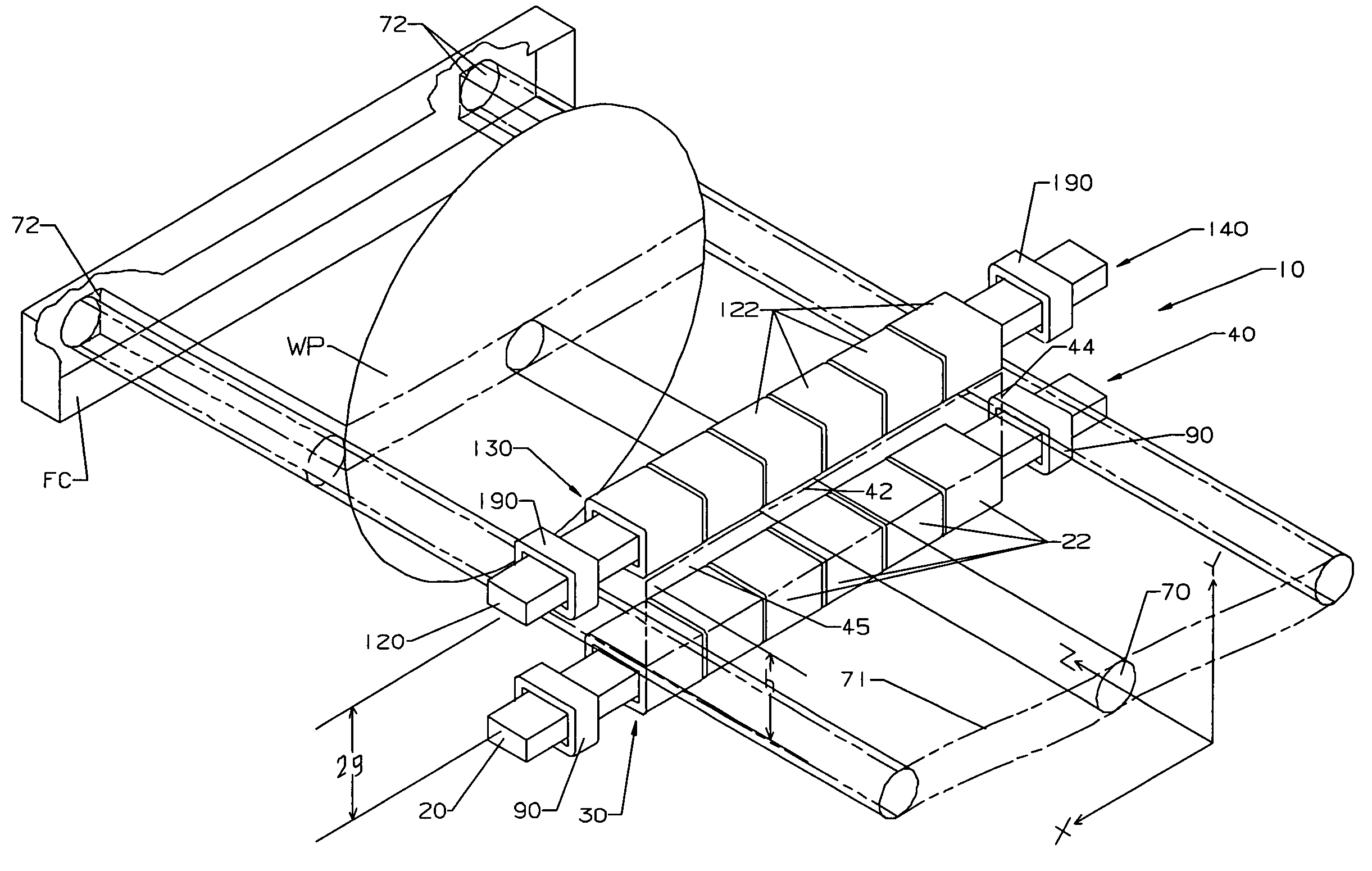
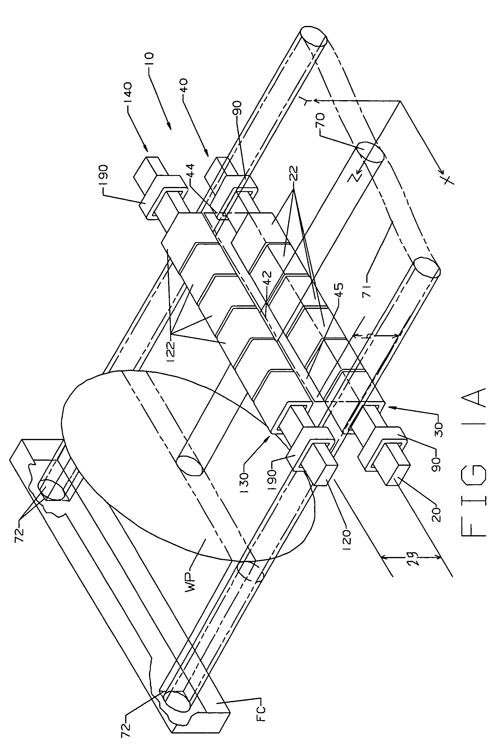
[0033] a spatial channel bounded by said multideflector sequence arrangements for applying a contiguous magnetic field and a pre-selected magnetic field gradient profile to a scanned ion beam traveling therethrough, wherein the parallelism for a scanned ion beam becomes finely controlled and more accurate.
[0039] applying said adjusted magnetic field gradient profile across the breadth of the beam such that said errors in the direction of the beam centroid are substantially eliminated relative to the plane at which the workpiece is to be implanted.
[0041] after applying said adjusted magnetic field gradient profile across the breadth of the beam such that said errors in the direction of the beam centroid are substantially eliminated relative to the plane at which the workpiece is to be implanted, measuring the average dose rate per unit length across the breadth of the scanned beam;
[0042] modifying the waveform that is applied to the beam scanner in response to the measured dose rate such that the errors in dose rate relative to a pre-defined desired dose profile are substantially reduced.

Problems solved by technology

Changes in the incident beam angle thus cause many undesired variations by shadowing and dopant placement in the process parameters, whose significance and magnitude is increased by the ever-shrinking dimensions of transistor size.
However, small variations in incident angle can cause significant variations in the alignment of the buried dopant.
This effort, however, tends to be a single adjustment covering an averaged beam direction; and there remains still a substantial residual individual trajectory variation in beam direction across the locus of the scanned beam within these systems.
It would theoretically be possible to reverse the tradeoff and achieve a very high degree of beam parallelism at the expense of uniform current density; but the individual parameters of beam parallelism and current uniformity cannot in general be simultaneously optimized.
This is a marked disadvantage and obstacle for many ion implantation applications which require both a high degree of particle trajectory parallelism and excellent uniformity of current density.

Method used


Image

  • Method and fine-control collimator for accurate collimation and precise parallel alignment of scanned ion beams
  • Method and fine-control collimator for accurate collimation and precise parallel alignment of scanned ion beams
  • Method and fine-control collimator for accurate collimation and precise parallel alignment of scanned ion beams

Examples


Embodiment Construction

[0058] The present invention comprises a method for accurate collimation and parallel alignment of a scanned ion beam; and provides an unique precision instrument, a fine-control collimator, for accurately adjusting and controlling the parallelism of the trajectories for the charged particles in a scanned ion beam.

[0059] Conventionally known and previously existing hybrid parallel-scanned ion implantation apparatus and systems typically have a device which functions as a coarse collimator and which generates approximately parallel ion trajectories for the charged particles in the scanned beam. The present invention provides precision refinements and fine controls for improving the parallelism of scanned beams in such ion implanters and systems, in which: [0060] (i) A reference axis of parallelism is defined, whose orientation and alignment with respect to the implantation plane for the silicon wafer (or other substrate) is accurately known; [0061] (ii) The angle direction of travel...


PUM


Abstract

In a system for implanting workpieces with an accurately parallel scanned ion beam, a fine-control collimator construct is used to reduce the deviation of the scanned ion beam from a specified axis of parallelism and thereby improve its collimation. The shape of the fine-control collimator matches the ribbon shape of the beam and correction of parallelism in two orthogonal directions is possible. Measurement of the non-parallelism is accomplished by sampling the scanned beam in two planes and comparing timing information; and such measurement is calibrated to the orientation of the workpiece in the plane where ion implantation occurs. Measurement of non-uniformity in the doping profile is accomplished using the same means; and the scan waveform is adjusted to substantially remove any non-uniformity in the doping profile.

Description

PRIORITY CLAIM [0001] The subject matter of the invention was first presented as U.S. Provisional Patent Application Ser. No. 60 / 511,417 filed 15 Oct. 2003 and entitled “Multipole Lens And Methods For Accurate Collimation And Alignment Of Scanned Beams”.FIELD OF THE INVENTION [0002] This invention relates generally to the production of parallel ribbon-shaped charged-particle beams; is directed to improving the parallelism of scanned ribbon-shaped ion beams used for treating workpieces with ions; and particularly concerns single wafer hybrid scan ion implantation systems in which a semiconductor wafer or other substrate is mechanically passed in one direction through a scanned ion beam which is applied at a higher frequency in an orthogonal direction. BACKGROUND OF THE INVENTION Intended Applications: [0003] In the field of ion implantation of semiconductors for transistor fabrication, there is a class of implants which is known as ‘parametric’ (sometimes also characterized as ‘medi...

Claims


Application Information

Patent Timeline
IPC IPC(8): H01J37/147H01J37/304H01J37/317
CPCH01J37/1472H01J37/1474H01J37/3045H01J2237/152H01J2237/1501H01J2237/1504H01J2237/1508H01J37/3171
Inventor WHITE, NICHOLAS R.
Owner WHITE NICHOLAS R
Learn More