Eureka AIR delivers breakthrough ideas for toughest innovation challenges, trusted by R&D personnel around the world.

Detection of transient phase shifts in any optical wave front with photorefractive crystal and polarized beams

Inactive Publication Date: 2005-04-21
OPTOINSPECTION
View PDF6 Cites 13 Cited by
  • Summary
  • Abstract
  • Description
  • Claims
  • Application Information

AI Technical Summary

Benefits of technology

[0016] The present invention also provides an apparatus for detection of the transient phase shift in any optical wavefronts, which generally includes a laser source for generating a laser beam with a predetermined frequency and an optical assembly for deriving two mutually coherent beams, one of which serves as a reference beam and another an object beam interacting with an object, for example by means of scattering or reflecting, to obtain a transient phase shift, for collecting the object and reference beams into the photorefractive crystal, and for causing the reference beam to interfere inside the photorefractive crystal with the object beam. The apparatus further includes a phase retardation optical element installed at least in one of the said beams for setting the proper polarization state and an optical assembly for collecting a beam, which is combined of the partially transmitted object beam and partially diffracted reference beam, into an optical detector for detecting the optical signal and converting it into an electrical signal representative of a transient phase shift. The apparatus may also includes a power supply for producing of an alternating electric voltage varying in time with a period shorter than the response time of the photorefractive crystal to apply to the photorefractive crystal so as to increase the strength of the dielectric-permittivity-tensor grating.

Problems solved by technology

It is also known that a real-time hologram recording in the diffusion mode leads to amplification of the object beam in expense of the reference beam.
However, such a phase shift affects on the hologram formation that leads to decreasing of the hologram efficiency and consequently, to a worse sensitivity.
However, the sensitivity of this method is diminished because of the optical energy loss from the polarization analyzer.
A real-time hologram created under such rapidly varying external electric field has the same phase shift compare to the input interference pattern as a hologram recorded in the diffusion mode, thus resulting in amplification of the signal beam.
However, the sensitivity is again limited by inevitable loss of the optical light energy in the polarization analyzer.

Method used


Image

  • Detection of transient phase shifts in any optical wave front with photorefractive crystal and polarized beams
  • Detection of transient phase shifts in any optical wave front with photorefractive crystal and polarized beams
  • Detection of transient phase shifts in any optical wave front with photorefractive crystal and polarized beams

Examples


example

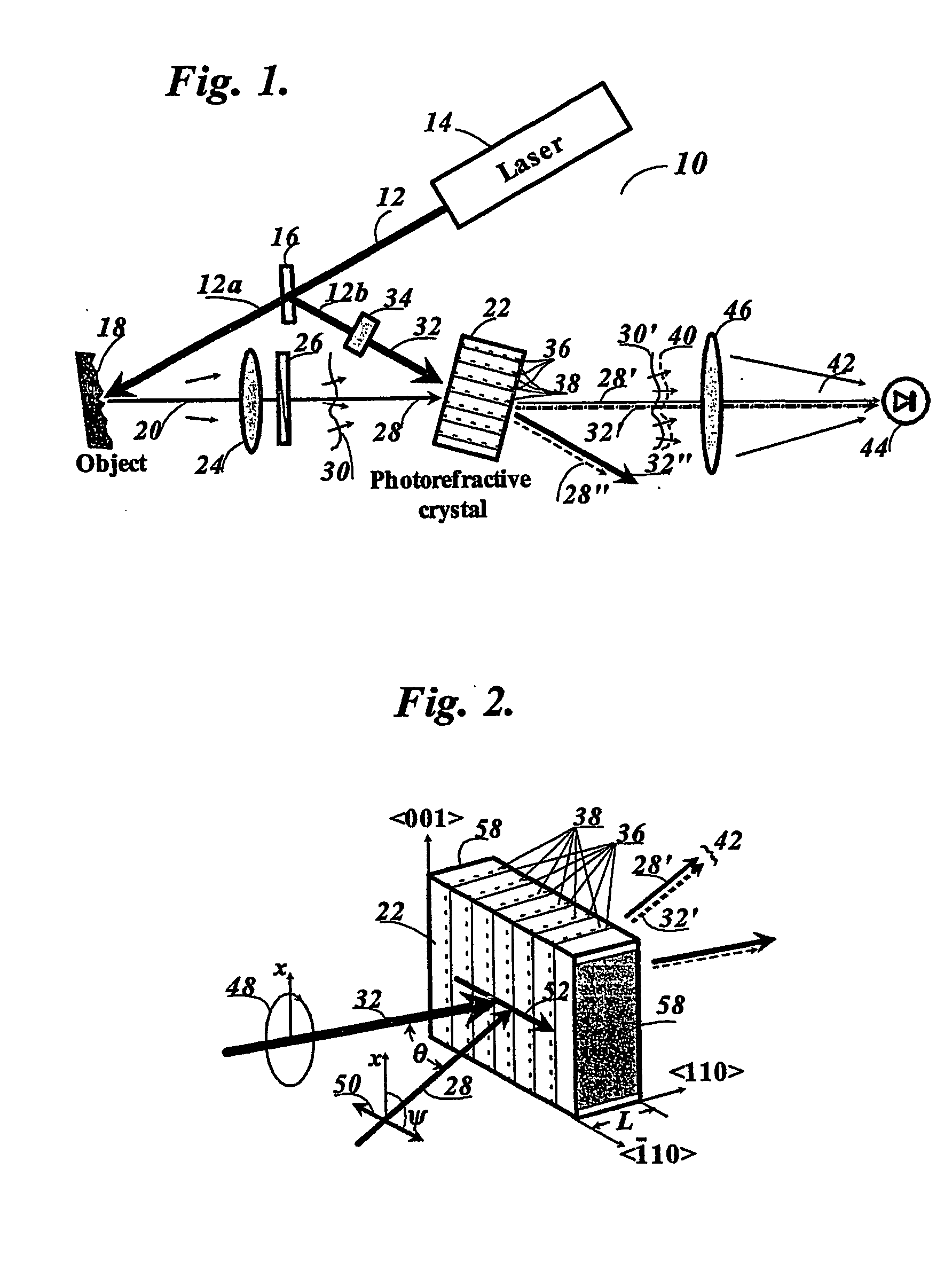
[0071] The photorefractive crystal 22 of Bi12TiO20 was cut in the parallelepiped shape similar to that shown in FIG. 2. The input face polished to the optical quality is orthogonal to the crystallographic axis . The thickness, L, of the crystal is equal to 1.97 mm. Gold electrodes were evaporated onto the faces that are orthogonal to the crystallographic axis . The distance between electrodes is equal to 1.95 mm. The third dimension of the crystal (along to the axis ) is equal to 5.48 mm.

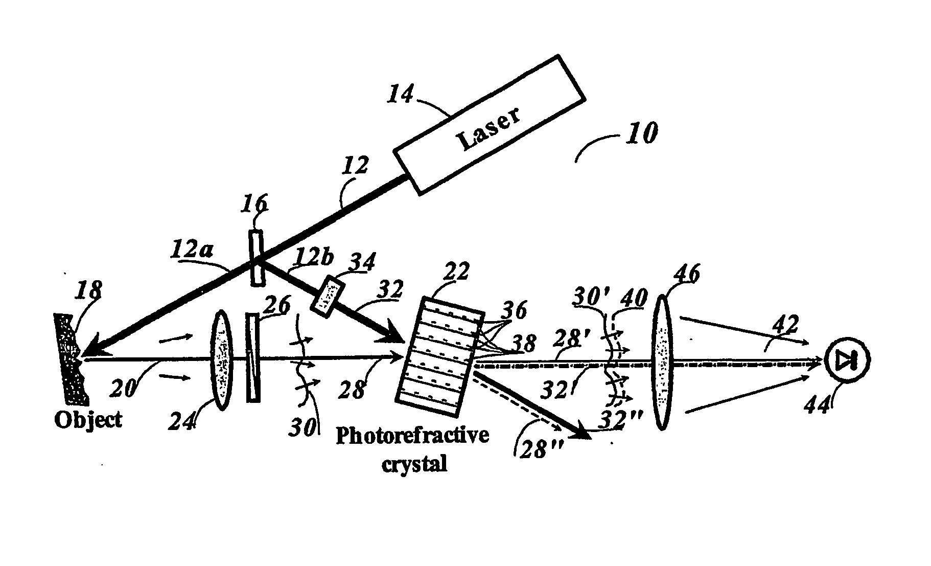
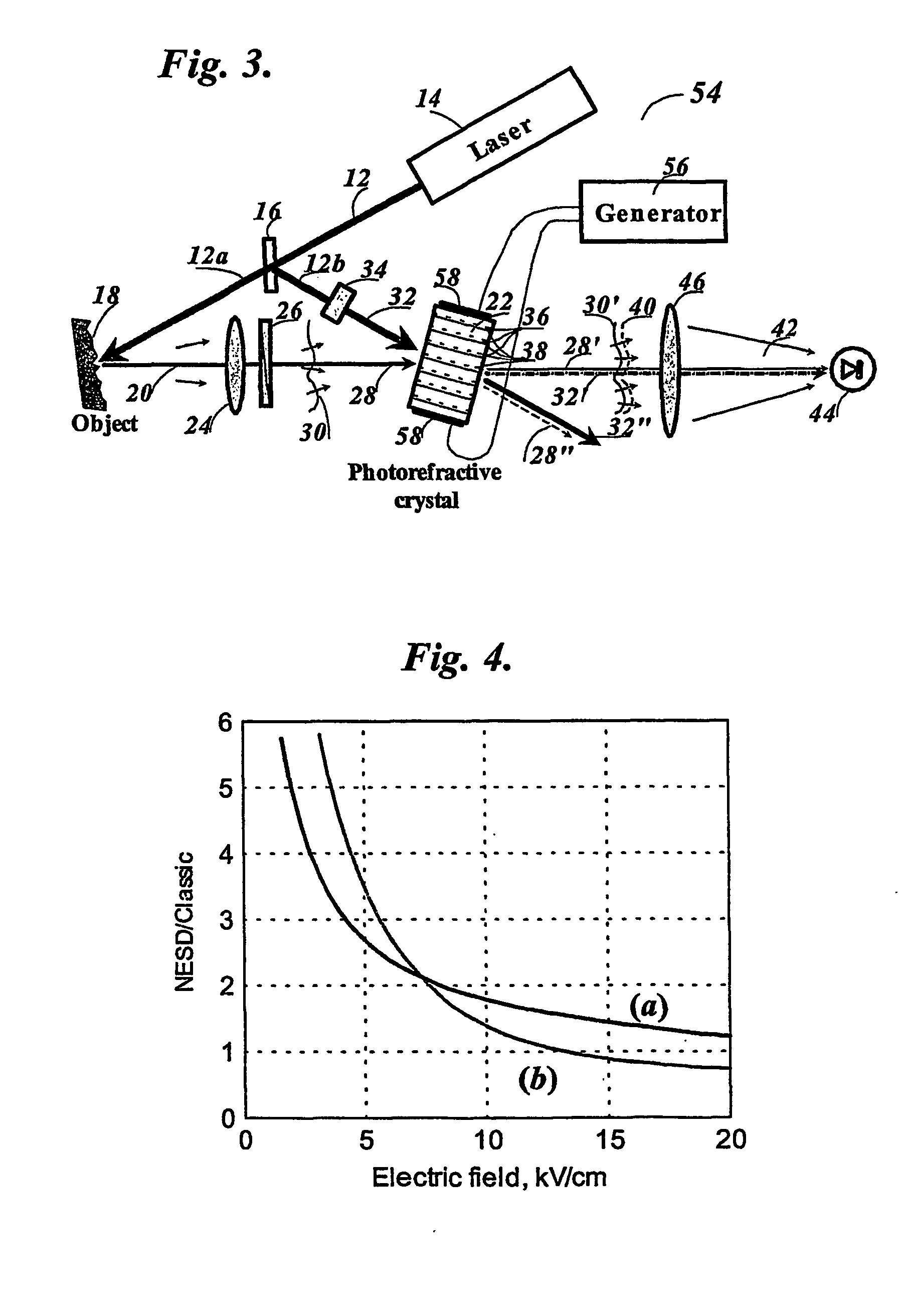
[0072] Further characterization of the photorefractive crystal 22 was carried out in the interferometer setup similar to that shown in FIG. 3, embodiment 54. In this characterization, a rough vibrating surface of a loudspeaker diffuser served as a surface under study 18. The loudspeaker was connected with a standard signal generator for excitation of diffuser vibrations at the frequency range 20 Hz-2 kHz. A high-voltage generator 56 electrically connected with the electrodes 58 of the photorefracti...


PUM


Abstract

Detecting transient phase shifts in an object laser beam of predetermined frequency having an arbitrary wavefront and apparatus for directing said object laser beam to cross a second reference laser beam coherent with said object beam into an oriented photorefractive crystal (22) (Bi12TiO20) (applied alternating electric field) belonging to the crystal symmetry group of 43m or 23, setting the polarization state of said object beam (20, 26) and said reference beams (32, 34) to be elliptical and different one from other, causing said object laser beam to interfere with said reference beam inside the said photorefractive crystal so as to form a dielectric-permittivity-tensor grating diffracting said reference beam into said object beam and vice versa, and directing a beam transmitted through the said photorefractive crystal in the direction of a transmitted object beam onto a photo-detector (44) to result in an electrical output signal that is representative of the transient phase shift in the object laser beam. Optical fibers and splitted object beams may be used.

Description

FIELD OF INVENTION [0001] The present invention relates to a method and apparatus for detecting a transient phase shift in any optical wavefronts. The invention is particularly directed toward detecting ultrasonic motion of a diffusely scattering or reflecting surface, which is very useful for remote nondestructive testing applications. Moreover, the invention is directed toward the measurements of small phase shifts of a complicated wavefront arising from a multimode optical fiber when it is subjected to bending, pressure, or another impact providing that such phase shift is representative of this impact. BACKGROUND OF INVENTION [0002] The detection of the phase modulation or frequency modulation of an optical wave is important for various fields of application where optical beams are used to detect the motion of the objects. This is the case of laser sensing of vibrations and laser detection of ultrasound and of transient body deformations such as those produced by a shock or on i...

Claims


Application Information

Patent Timeline
IPC IPC(8): G01H9/00G01N29/24G01N29/50
CPCG01H9/00G01N29/2418G01N2291/0427G01N2291/0423G01N29/50
Inventor KAMSHILIN, ALEXEI AGRACHEV, ALEXANDER
Owner OPTOINSPECTION
Why Eureka
Eureka Blog
Learn More