Heating apparatus using surface acoustic wave

a technology of surface acoustic waves and heating apparatus, which is applied in the field of heating apparatus using surface acoustic waves, can solve the problems of insufficient research on the mechanism of this phenomenon, and achieve the effects of excellent temperature stability, rapid heating, and short tim

Inactive Publication Date: 2005-04-21
MEDICAL & BIOLOGICAL LAB CO LTD +1
View PDF1 Cites 22 Cited by
  • Summary
  • Abstract
  • Description
  • Claims
  • Application Information

AI Technical Summary

Benefits of technology

[0008] In addition, the substrate temperature did not exceed 100° C., even if applied voltage was increased to the degree in which the water retained on the piezoelectric substrate was atomized. The result shows that the SAW is effective as a heating method in case that the boiling of the object for heating must be avoided. In addition, it means that the heating by the SAW is excellent in the temperature stability.
[0009] In addition, it was found that the thermal effect by the SAW was achieved in short time. It was indicated that there was large utility value on

Problems solved by technology

However, the research on the mechanism

Method used


Image

  • Heating apparatus using surface acoustic wave
  • Heating apparatus using surface acoustic wave
  • Heating apparatus using surface acoustic wave

Examples


example 1

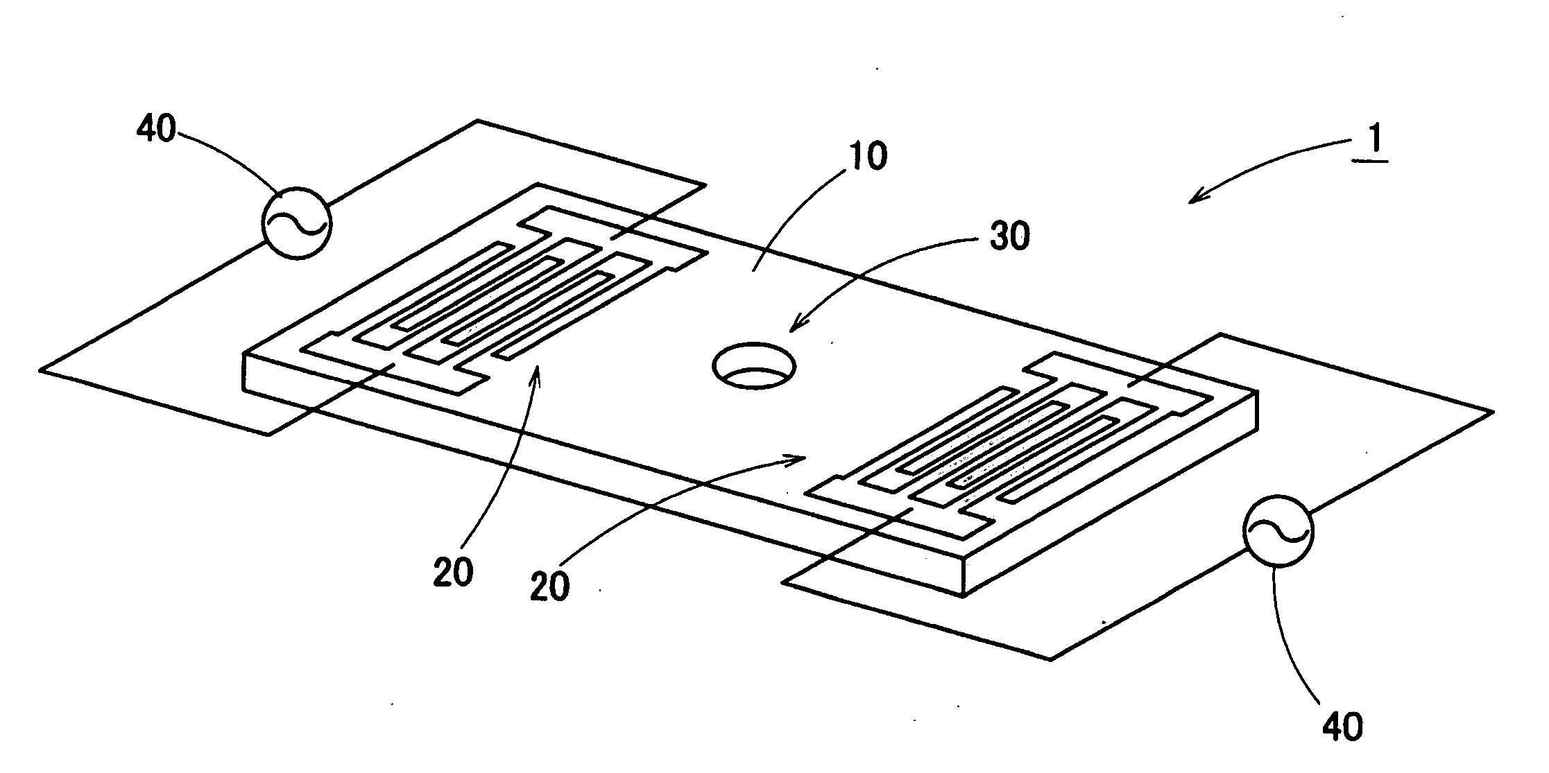
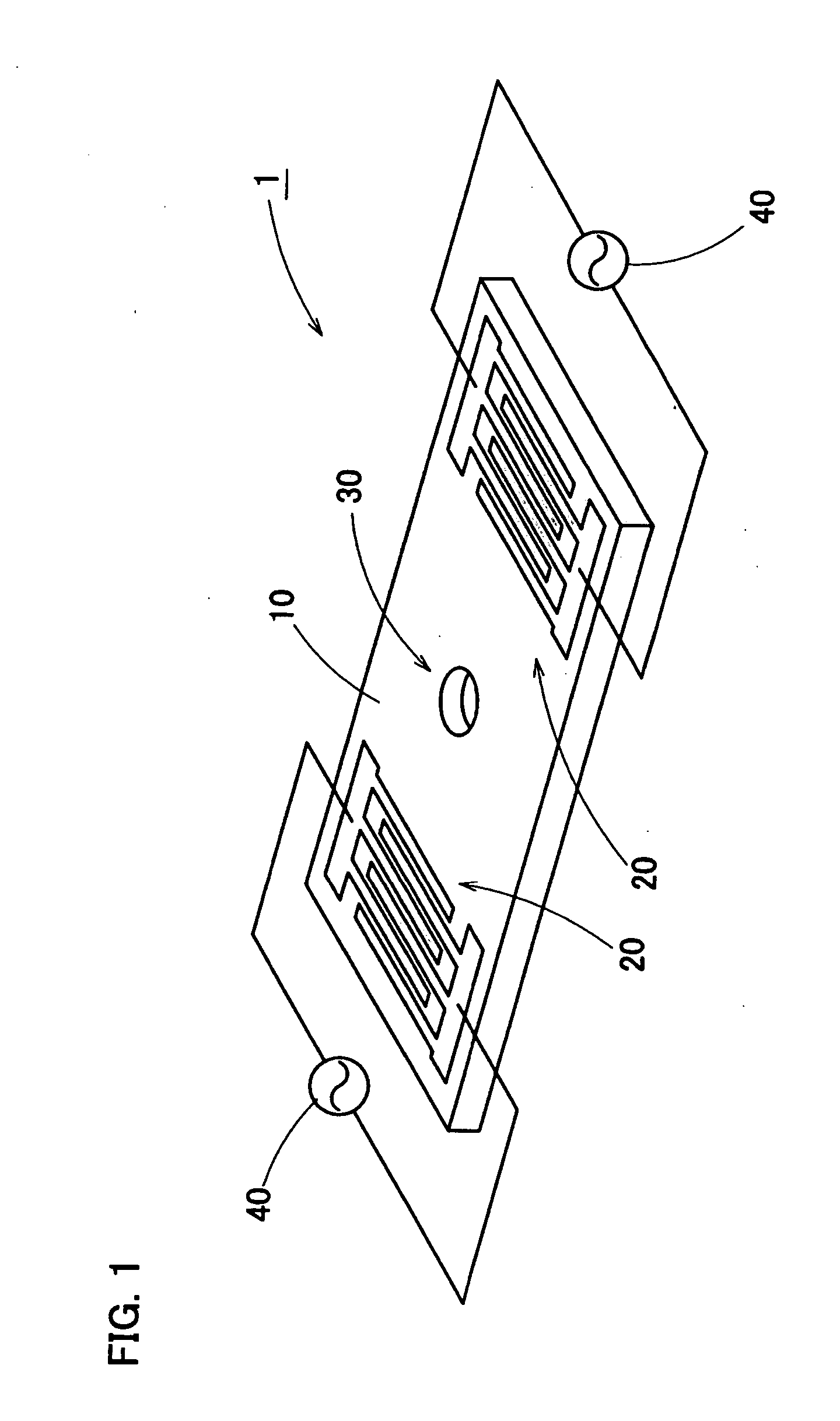
[0079] In FIG. 1, the schematics of surface acoustic wave heater (call “the SAW heater”) 1 which concerns this invention is shown. The SAW heater 1 has piezoelectric substrate 10, two inter-digital transducers 20 and thermal reaction part 30. The piezoelectric substrate 10 is made of 128 degree rotated Y cut X propagation lithium niobate (128° XY-LiNbO3). Each inter-digital transducer 20 made of Au / Cr is formed on the surface of the piezoelectric substrate 10 in order to hold the thermal reaction part 30 from right and left. And, the distance between each inter-digital transducer 20 and thermal reaction part 30 is equal.

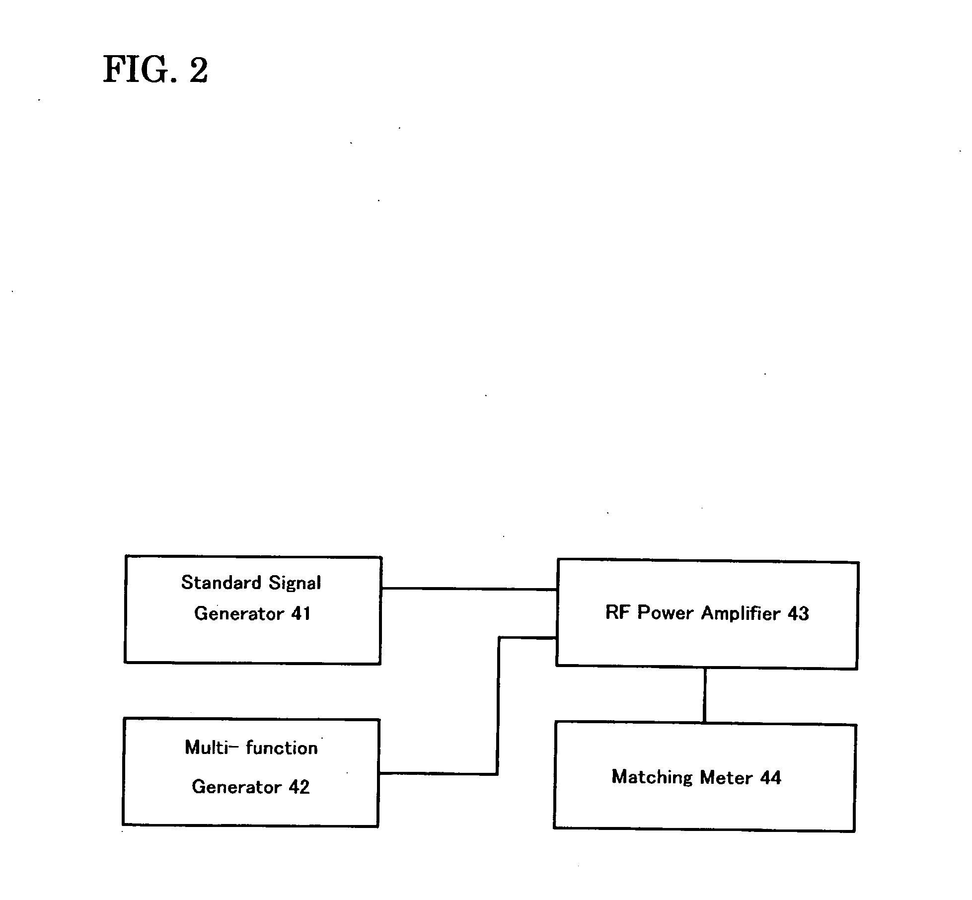
[0080] The high frequency power source 40 is connected with each inter-digital transducer 20. As shown in FIG. 2, high frequency power source 40 contains the circuit that standard signal generator 41, multi-function generator 42, RF power amplifier 43, matching meter 44 were connected. Thermal reaction division 30 consists of the cylindrical concavity formed on the ...

example 2

[0083] Other example is shown in FIG. 3. By appending the identical reference number to the element which is identical with that in the previous practical example and thereby its description is omitted.

[0084] In surface acoustic wave heater (the SAW heater) 1a of this example, circular arc type electrode (IDT) 21 is used, and the surface acoustic wave is converged by this, and the improvement in the heating efficiency is attempted. On piezoelectric substrate 10, the region which concentrates surface acoustic wave has been covered in a metal (for example, gold) thin film in the round shape. In SAW heater 1a, the upper surface of this metallic thin film becomes thermal reaction part 35.

example 3

[0085] Further example is shown in FIG. 4. By appending the identical reference number to the element which is identical with that in the previous practical example and thereby its description is omitted.

[0086] For the example of the surface acoustic wave heater (SAW heater) 1b, piezoelectric devices 15, SAW propagation substrate 50 are used. Piezoelectric device 15 consists of piezoelectric substrate 16 and electrodes 22 for the bulk wave excitation. Electrode 22 for the bulk wave excitation has been formed in order to substantially cover the whole of piezoelectric substrate 16 of upper and bottom surface. In other words, electrode 22 for the bulk wave excitation is holding piezoelectric substrate 16.

[0087] SAW propagation substrate 50 is made of the glass, and it has gratings 51 made of metal layers stripe fabricated on the upper surface. In addition, thermal reaction part 35 which consists of a metallic thin film has been formed in the upper surface of SAW propagation substrate...


PUM


Abstract

The present invention provides new applications for surface acoustic waves. A heating apparatus with a surface acoustic wave generator is disclosed. In one embodiment of the invention, a heating apparatus comprise a surface acoustic wave generator having a piezoelectric substrate and inter-digital transducers (IDT) formed on the piezoelectric substrate, and a thermal reaction part is formed at the part of the piezoelectric substrate.

Description

CROSS REFERENCE TO RELATED APPLICATIONS [0001] This application claims priority to Japanese application No. 2003-322485, filed Sep. 16, 2003 and Japanese application No. 2004-009890, filed Jan. 16, 2004. The contents of the applications numbered 2003-322485 and 2004-009890 are hereby incorporated by reference in their entirety. FIELD OF THE INVENTION [0002] This invention relates to apparatus using surface acoustic waves. More specifically, it relates to heating apparatus using surface acoustic waves, methods using thereof and the like. BACKGROUND OF THE INVENTION [0003] The device using surface acoustic wave (also referred to as “SAW”) is widely utilized as high frequency filters for portable telephone, TV or VTR. And also, it is applied to various detectors such as the gas sensor, etc. and ultrasonic atomizer, ink jet printer, wipers, fuel injection system of the liquid (see JP 5-5869 A, JP 5-34349A, JP 7-232114A, JP 8-140898, JP 9-201961A, and JP 10-193592 A). [0004] On the other...

Claims


Application Information

Patent Timeline
IPC IPC(8): F24J3/00B01J19/10H03H9/25H04R1/00H05B1/00
CPCH05B6/686A61N7/00B05B17/0607
Inventor SHIOKAWA, SHOKOMATSUI, YOSHIKAZUKONDOH, JUN
Owner MEDICAL & BIOLOGICAL LAB CO LTD
Why Eureka
Try Eureka