However,
neon lighting technology demands extremely high operational voltages, in the range of 3,000-15,000 volts.
Neon lighting does not, in general, permit the intensity of the output light to vary, i.e., the light is not dimmable.
Building codes and safety concerns prohibit
neon lighting from being used in applications such as lighted trim that frames a window and lighting for swimming pools.
Neon lights are typically made of blown glass, and the shape configuration cannot be altered once the shape has been formed into the final product.
Neon lighting is non-portable, and only a single color may be displayed in any one neon tube.
Therefore applications for temporary or portable signage, lighting or lighted trim are not well served by neon technology.
Neon technology cannot support any application where changing color is desired within a tube, plane, or other volume.
Fluorescent lighting also suffers similar limitations since fluorescent lighting requires high voltages to operate and the bulbs are extremely fragile.
Fluorescent lights have a
limited service lifetime, which necessitates changing bulbs with some frequency.
Fluorescent lighting technology suffers from additional limitations: Fluorescent lighting systems that can vary the output intensity are unrealistically expensive.
Fluorescent lighting has a single or fixed spectral output in any one tube, and many desirable colors or spectral distributions are not producible by fluorescent technology.
The output spectrum of a
fluorescent light is limited to the excitation energy of the gas within the tube, and there is no combination of gas that optimizes the output spectrum for the
human eye.
This causes considerable eye strain and reduced
clarity when used to illuminated interior spaces such as office environments.
Additionally, fluorescent lights operate typically at 60
hertz AC power, causing
flicker and increasing the induced eye strain.
Therefore, while both neon and fluorescent lighting enjoy large markets, both technologies suffer from many deficiencies which include, but are not limited to, cost, safety, lifetime, lack of flexibility and alterability, lack of ability to alter color, lack of ability to dim or change intensity, portability, and sub-optimized output spectrums.
This means that at each reflection around 1 to 5% of the power is lost with each reflectance.
If you have a mirror
waveguide that is even 20 meters long, this adds up to a lot of reflections and hence a lot of
power loss.
When using light guides to produce neon-like effects, the prior art is limited to focusing a
light source onto the end of these light guides, and then dispersing or scattering the light out the side of the light guide through special coatings in the cladding or by
cutting or deforming the cladding in some way, or by bending the tubing at angle that exceed the limits of TIR reflectance.
Both glass and plastic light guides suffer significant deficiencies if they are to be used in applications to replace neon technology.
Light guides of this type are expensive and rigid at the diameters required for neon-like effects.
Both glass and
fiber light guides suffer from the high cost of the
light source required to illuminate the light guides.
These light sources are cumbersome to use and have a low efficiency.
In addition, every interface that light must transmit through imposes a reflective or absorptive loss.
Absorptive and reflective losses also occur when light is sent through any color filter.
In addition, for light guides that are composed of multiple
fiber optic fibers in a bundle, light is lost at the interstices between these fibers when light impinges on the cladding instead of the core.
All of these losses not only reduce the amount of
transmitted light but result in a buildup of heat within the light
source system, and at the front end of the light guide, which must be eliminated from the
system for safety reasons or to reduce degradation of the light guide materials.
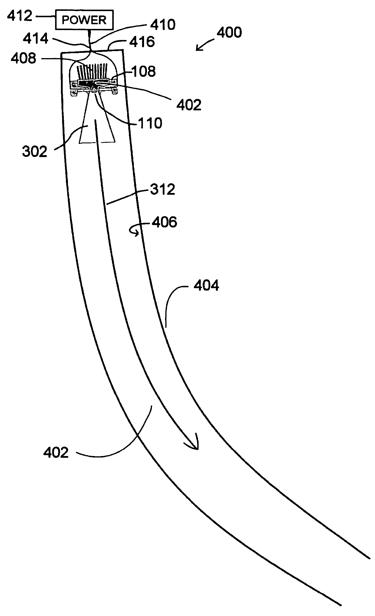
One of the remaining challenges for this type of lighting is to create light sources that can be embedded within the core fluid to provide enough
optical power to meet neon-like and other lighting applications.
However, these high-power LEDs generally have a wide dispersion angle (Lambertian dispersion), which makes them very inefficient to couple to most light guides using TIR, where the TIR effect requires some collimation of the light source.
In addition, these high-power LEDs produce a significant amount of
waste heat.
Unless this
waste heat is removed from the device, the temperature at the LED junction will quickly raise to the point where production of light is very inefficient or the LED device fails.

