
Oil/gas separation membrane, its use in gas sensor and process for producing the same

a gas sensor and separation membrane technology, applied in the field of oil/gas separation membrane, can solve the problems of powerless detection of faults that have developed quickly, separation of gases must be carried away, method still suffers an obvious drawback, etc., and achieves the effect of not losing mechanical properties and permeation efficiency

Inactive Publication Date: 2005-04-28
ASENSOR TECH
View PDF9 Cites 46 Cited by
  • Summary
  • Abstract
  • Description
  • Claims
  • Application Information

AI Technical Summary

Benefits of technology

[0016] A primary object of the present invention is to provide an oil / gas separation membrane for solving above mentioned drawbacks of fault gas detection / monitoring system, wherein the oil / gas separation membrane is capable of withstanding high temperature and negative pressure (i.e. vacuum) without losing mechanical property and permeation efficiency.
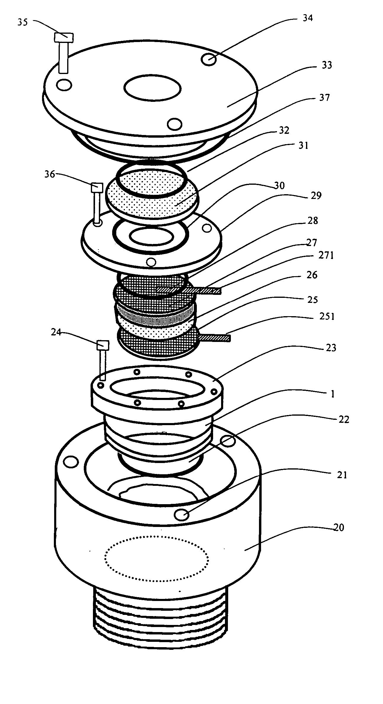
[0018] Another object of the present invention is to provide a gas sensor for detecting and monitoring fault gas of oil-filled electric systems, wherein no complicated mechanical wearing and moving parts such as pumps and valves are applied, and in the mean time the gas sensor is capable of operating normally under various temperature and pressure conditions.

Problems solved by technology

When a fault is developed in a transformer, an immediate consequence would be a local overheating or a local electric discharging accompanied with high energy releasing.
However, this method still suffers an obvious drawback.
Therefore, it is powerless to detect those faults developed quickly between two scheduled analysis time period.
The drawback is that the separated gases must be carried away by a carrier (usually use dry air or inert gas) or a gas pump to reach the sensing element or a sensing device.
Therefore the complicated whole system will more or less reduce the reliability.
The drawback is that the thin polymer membrane is venerable to deformation and damage under condition of negative pressure (vacuum) and high temperature, resulting in the drift of sensor calibration, and to a worse extent, resulting to oil leaking as well as the permanent damage of the sensor.
Even such membrane is stronger than the unsupported one, but is still fragile and subject to the deformation and damage under harsh conditions (temperature and pressure).
This method is effective for preventing the deformation of polymer membrane to some extent, but is still less satisfied for resolving the fundamental problem mentioned above.
Moreover, the covering of the metal plate or screen on the membrane surface will impair the oil convection over the membrane and reduce the contact surface of the membrane, therefore negatively affecting the separation efficiency.
This further reduces the reliability of the system.

Method used


Image

  • Oil/gas separation membrane, its use in gas sensor and process for producing the same
  • Oil/gas separation membrane, its use in gas sensor and process for producing the same
  • Oil/gas separation membrane, its use in gas sensor and process for producing the same

Examples


example 1

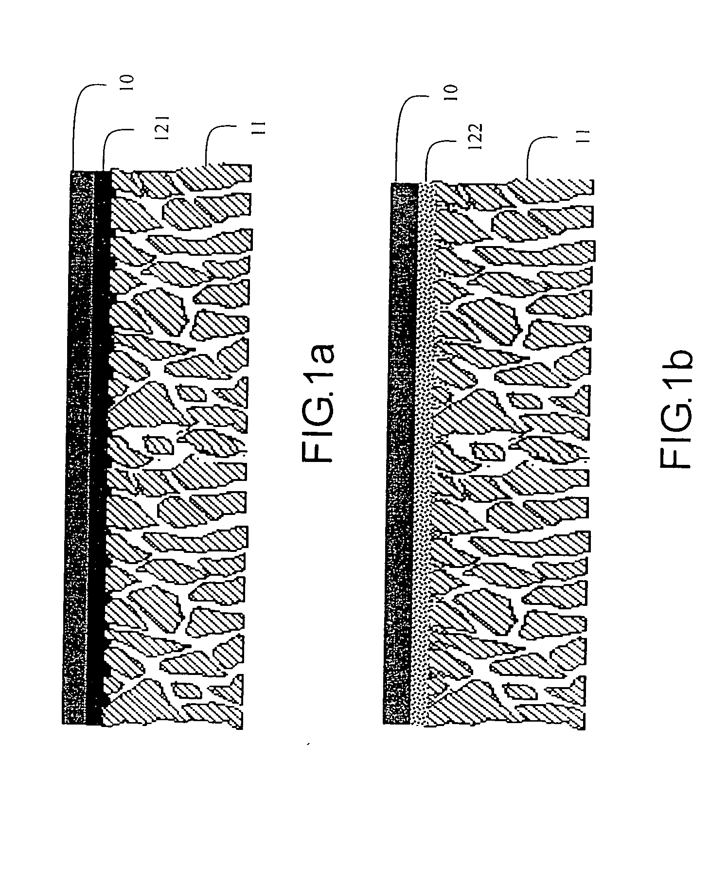
[0065] Bulk polymer membrane: the selected membrane must be stable, oil-resistant, temperature-resistant, permeable to fault gases and impervious to oil. In practice, PTFE, PVDF, PFEP, and PFA are good choices. According to the preferable embodiment, PTFE membrane obtained from Saint-Gobain Advanced Materials, Taiwan, is applied. It is worth to mention that thickness of the membrane is ranged between 0.01 to 0.5 mm, preferably, ranged between 0.025 to 0.125 mm.

example 2

[0066] Porous metal frit disk: the selected porous metal frit disk is prepared by metal powders under a high temperature and a high pressure circumstance. It is noted that the metal frit disk must have a good mechanical strength to support the bulk polymer membrane, and a high porosity to allow quasi resistant-free gas permeation.

[0067] In practice, the stainless steel, bronze and nickel are good choices. The preferred embodiment of the present invention utilizes the sintered stainless steel frit disk obtained from GKN Sinter Metals, Germany, with the porosity greater than 20%, preferably between 35-55%, pore size between 0.001-0.1 mm, preferably between 0.005-0.02 mm, and thickness between 1-5 mm.

example 3

[0068] Adhesive: the selective adhesive must have good chemical compatibility with the polymer membrane and porous metal frit, and more importantly have extremely high gas permeability so that the presence of this adhesive will affect very little, if not, the overall gas permeation. There are two preferred embodiments in the present invention:

[0069] First, a solution made with amorphous high permeable polymer, namely (tetrafluoroethylene) / (2,2-bis-perfluoromethyl-4,5-difluoro-1,3-dioxole) copolymer, or P (TFE / PFD) from E.I. Du Pont de Nemours and Company, Wilmington, Del. The copolymers are available under the Trade NameTeflon AF” in grades such as 1600 and 2400, having Tg's of 160 and 240° C., respectively. The difference between Teflon AF 2400 and Teflon AF 1600 is in their mole ratio of TFE / PFD which are 13% / 87% and 35% / 65%, respectively. Teflon AF has permeability 1-2 magnitudes higher than bulk PTFE membrane, taking hydrogen as an example, the H2 permeability in PTFE is 7.4 ...


PUM

PropertyMeasurementUnit
Temperatureaaaaaaaaaa
Lengthaaaaaaaaaa

Abstract

An oil gas separation membrane combines a gas permeable yet oil and temperature resistant bulk polymer membrane such as poly(tetrafluoroethylene) and poly(tetrafluoroethylene-co-hexafluoropropylene); a porous metal support such as sintered metal frit disk made with stainless steel, bronze or nickel; and an highly gas permeable adhesive that bonds firmly the bulk polymer membrane and the metal frit surface together. The adhesive is either a homogenous polymer that has desirable gas permeability, or a coalescent porous polymer particulates network. A gas sensor employing the oil gas separation membrane for detecting and monitoring fault gases of oil filled electrical equipment requires no mechanical wearing or moving part such as pump and valve and the gas sensor is operated normally under various temperature and pressure conditions.

Description

BACKGROUND OF THE PRESENT INVENTION [0001] 1. Field of Invention [0002] This invention relates to on-line detection and monitoring method and apparatus of oil-filled electric equipments, more particularly, relates to an oil / gas separation membrane applied for monitoring fault gas within the oil-filled electric equipments, a method for preparing such oil / gas separation membrane, as well as a gas sensor equipped with such oil / gas separation membrane. [0003] 2. Description of Related Arts [0004] Generally, Oil-filled electric equipment refers to those electric equipments employing dielectric liquid (i.e. insulating oil) as dielectric medium, such as transformer, shunt reactor, tap changer and so on. Needless to say, a reliable and safe operation of these important equipments is the key factor for ensuring efficient power generation, transmission and distribution. [0005] For instance, the incipient fault detection and monitoring system for a transformer could significantly reduce the op...

Claims


Application Information

Patent Timeline
IPC IPC(8): B01D19/00C10G31/11G01N1/40G01N27/12G01N33/22
CPCB01D19/0031C10G31/11Y10T156/10G01N2001/4016G01N33/2841
Inventor QIN, REN YAN
Owner ASENSOR TECH
Learn More