Very thin, high carbon steel wire and method of producing same

a high carbon steel wire and ductility technology, applied in the field of very thin, can solve the problems of deterioration of high carbon steel wire, ineffective prevention of delamination, and inability to achieve ductility of each very thin wire, so as to prevent the occurrence of delamination, and improve the ductility of steel wire.

Active Publication Date: 2005-04-28
KOBE STEEL LTD
View PDF6 Cites 31 Cited by
  • Summary
  • Abstract
  • Description
  • Claims
  • Application Information

AI Technical Summary

Benefits of technology

[0025] In the present invention it is intended to prevent the occurrence of delamination of a very thin, high carbon steel wire during torsional deformation in a high-speed stranding work even when the steel wire substantially contains N. To this end, in the very thin, high carbon steel wire according to the present invention, the foregoing specific exothermic peak in the differential scanning thermoanalysis curve is controlled (fixing of N atoms to dislocation in the steel wire structure is m

Problems solved by technology

Particularly, as the strength becomes higher than 4200 MPa, the ductility of each very thin, high carbon steel wire is deteriorated.
However, even by the above conventional proposed techni

Method used


Image

  • Very thin, high carbon steel wire and method of producing same
  • Very thin, high carbon steel wire and method of producing same
  • Very thin, high carbon steel wire and method of producing same

Examples


example 1

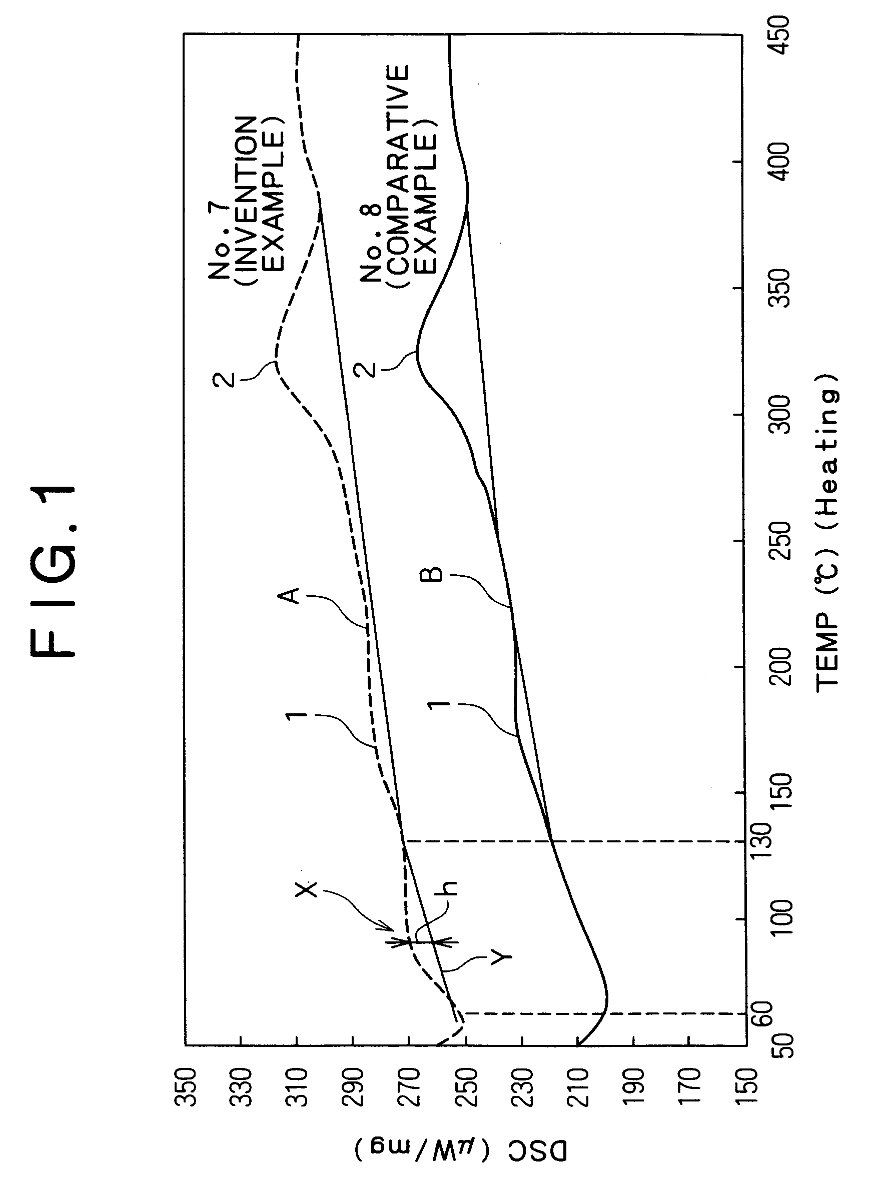
[0088] Working examples of the present invention will be described below. As Example 1, very thin steel wires were produced while changing the above wet lubrication wire drawing conditions variously to afford very thin steel wires, then the presence or absence of the foregoing exothermic peak X in DSC of each of the very thin steels wires, the maximum height h of the exothermic peak, and delamination characteristic, were evaluated.

[0089] More specifically, high carbon steel billets of compositions A to X in Table 1 below were subjected to hot rolling to produce steel wire rods, then the steel wire rods were subjected to wire drawing and patenting treatment under the wire diameter and strength conditions shown in Table 2 below to obtain a pearlite structure, followed by wet lubrication wire drawing to afford very thin steel wires.

[0090] In both examples according to the present invention and comparative examples, patenting treatment was conducted in the following manner. Heating wa...

example 2

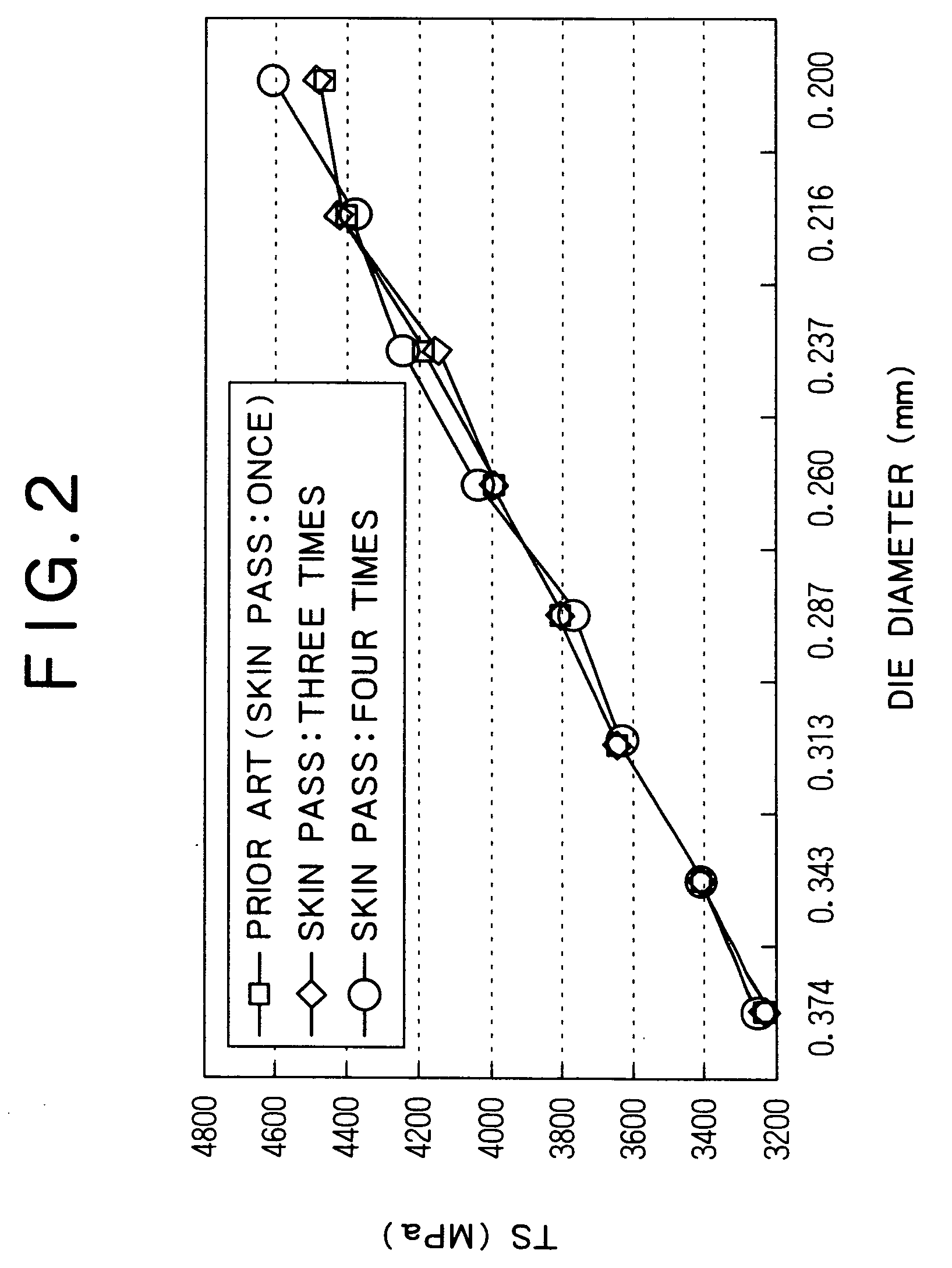
[0099] Next, high carbon steel wire rods of the compositions A to X shown in Table 1 were subjected to the same treatment as in Example 1 and then to wet lubrication wire drawing in the same way as in Example 1 while setting the reduction of area in each die, wire passing rate (Di2×v), lubricant liquid temperature, and skin pass wire drawing conditions, within the respective preferred ranges. Then, the wire drawability of very thin steel wires after the wet lubrication wire drawing, the presence or absence of the exothermic peak X in DSC with respect to the very thin steel wires, the maximum height h of the exothermic peak X, and delamination characteristic, were evaluated in the same manner as in Example 1, the results of which are set forth in Table 3.

[0100] As is apparent from Table 3, very thin, high carbon steel wires of Examples 18 to 30 according to the present invention comprise chemical components A to M, respectively, which fall under the scope of the present invention, a...


PUM

PropertyMeasurementUnit
Temperatureaaaaaaaaaa

Abstract

The very thin, high carbon wire is 0.05 to 0.50 mm in diameter and comprises, in mass %, 0.90-1.20% of C, 0.05-1.2% of Si, 0.2-1.0% of Mn, and 0.0050% or less of N, with the balance being iron and impurities. In a differential scanning thermal analysis curve A of the steel wire, the steel wire has an exothermic peak X in the temperature range of 60° to 130° C., and a maximum height h of the exothermic peak X relative to a reference line Y joining the point of 60° C. and the point of 130° C. in the differential scanning thermal analysis curve is set at 5 μW/mg or more. The very thin, high carbon steel wire is free of delamination in high-speed stranding and superior in both strength and ductility.

Description

BACKGROUND OF THE INVENTION [0001] 1. Field of the Invention [0002] The present invention relates to a very thin, high carbon steel wire having a high strength and superior in high-speed strandable ductility, as well as a method of producing the same. [0003] 2. Description of the Related Art [0004] A very thin, high carbon steel wire having a diameter of 0.05 to 0.50 and a strength as high as 4200 MPa or more has come to be used as steel cord or as saw wire for cutting a semiconductor. Generally, the very thin, high carbon steel wire is produced by subjecting a steel wire rod of 4.0 to 5.5 mm in diameter which has been subjected, as necessary, to hot rolling and subsequent conditioned cooling to primary wire drawing, subsequent final patenting treatment and further wire drawing. [0005] More particularly, the above patenting treatment involves heating the steel wire rod to a temperature range (750-1100° C.) of A3 point or higher for treatment to γ phase, subsequent quenching and allo...

Claims


Application Information

Patent Timeline
IPC IPC(8): B21C1/04B21C1/00B21C9/00B21C37/04C21D8/06C21D9/52C22C38/00C22C38/02C22C38/04C22C38/54
CPCB21C1/04B21C9/005B21C37/047C22C38/04C21D9/525C21D2211/009C22C38/02C21D8/06
Inventor NAGAO, MAMORUKURODA, TAKESHIMINAMIDA, TAKAAKI
Owner KOBE STEEL LTD
Why Eureka
Try Eureka