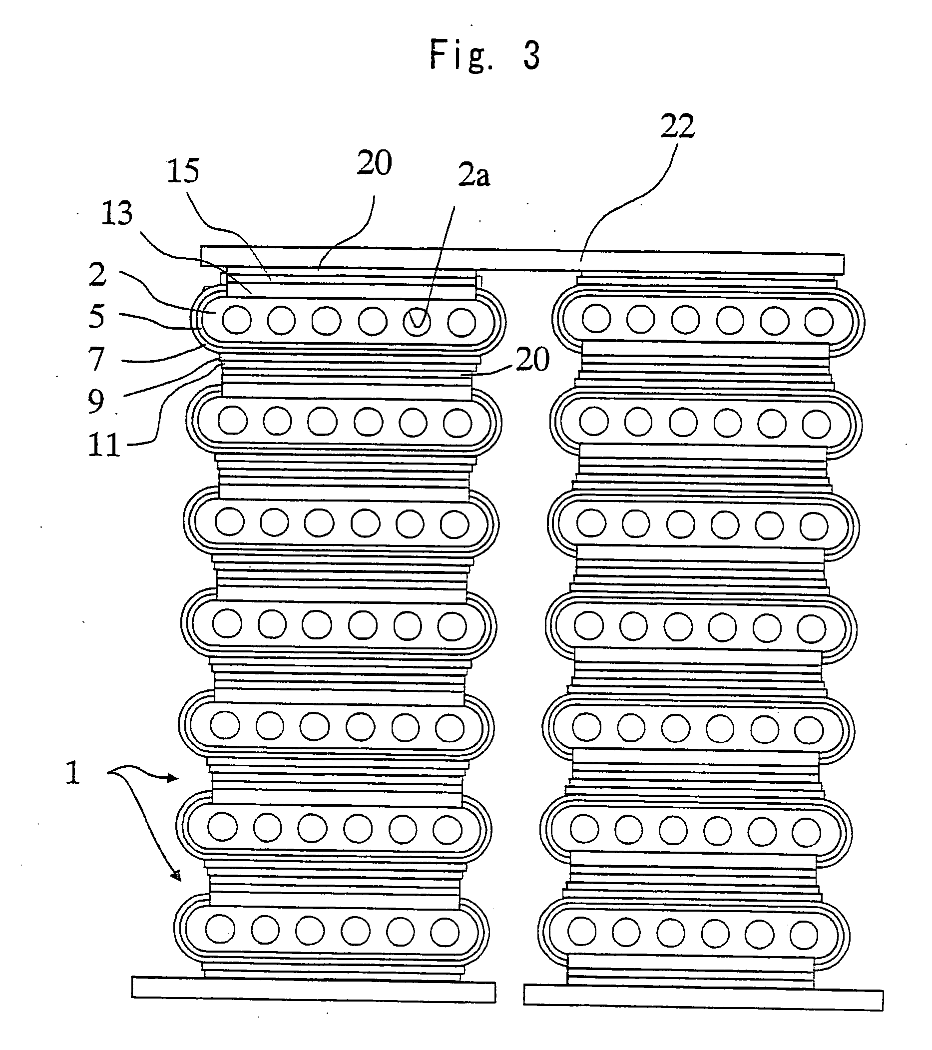
Fuel cell

a fuel cell and solid electrolysis technology, applied in the manufacture of cell components, electrochemical generators, final product manufacturing, etc., can solve the problems of insufficient function of oxygen electrode layers and drop in fuel cell performance, and achieve the effect of reducing interfacial resistance and increasing junction strength

Active Publication Date: 2005-05-05
KYOCERA CORP
View PDF0 Cites 7 Cited by
  • Summary
  • Abstract
  • Description
  • Claims
  • Application Information

AI Technical Summary

Benefits of technology

[0011] It is therefore an object of the present invention to provide a solid electrolytic fuel cell having a structure of forming a reaction-preventing layer between the oxygen electrode and the solid electrolytic layer, having a decreased interfacial resistance between the oxygen electrode and the reaction-preventing layer, and featuring an increased junction strength between the oxygen electrode and the reaction-preventing layer.
[0012] Another object of the present invention is to provide a solid electrolytic fuel cell capable of maintaining a sufficiently large output without spoiling the properties of the oxygen electrode despite of the formation of the reaction-preventing layer.
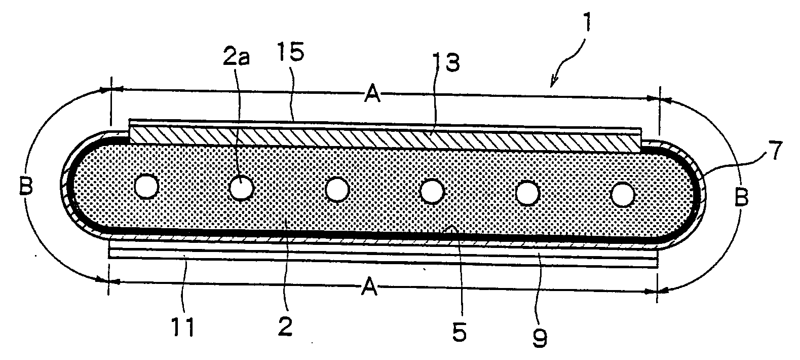
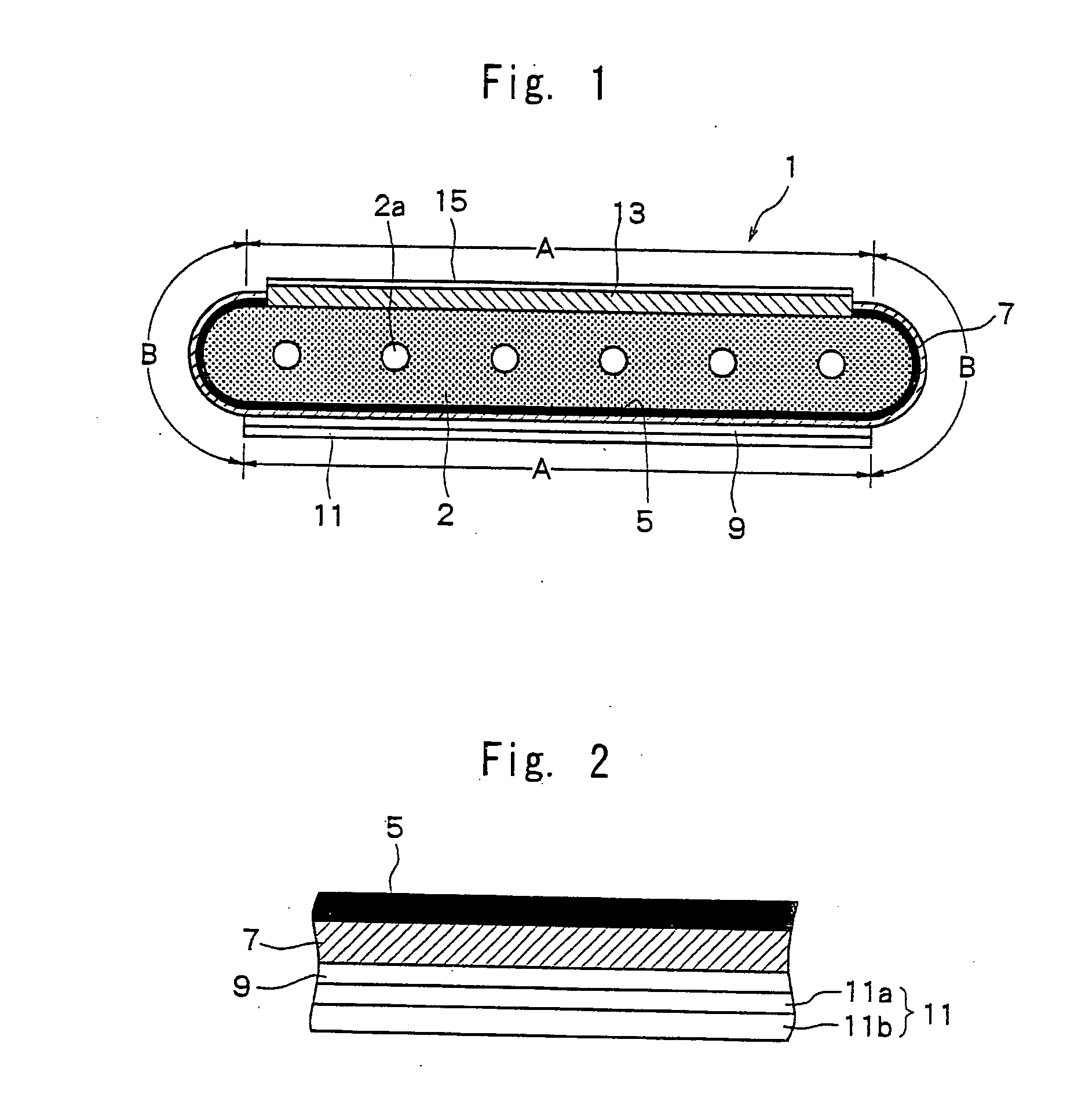
[0028] In the oxygen electrode layer of the two-layer structure of the present invention, the inner layer located on the reaction-preventing layer contains both particles of the oxide for preventing the diffusion of elements, forming the reaction-preventing layer, and particles of the perovskite composite oxide forming the surface layer of the oxygen electrode layer. Besides, the inner layer is densely formed as compared to the surface layer. Therefore, the interfacial resistance can be decreased between the oxygen electrode layer (inner layer) and the reaction-preventing layer, the junction strength can be increased between the oxygen electrode layer and the reaction-preventing layer, and the oxygen electrode layer is effectively prevented from being peeled off the reaction-preventing layer.
[0029] In the present invention, further, the inner layer of the oxygen electrode layer is formed for decreasing the interfacial resistance to the reaction-preventing layer and for increasing the junction strength. It is therefore desired that the inner layer of the oxygen electrode layer is formed having a thickness smaller than that of the surface layer so will not to lower the properties of the oxygen electrode layer. Further, the oxygen electrode layer of the double-layer structure is so formed that the electrode function index W defined by the above formula (1) is 300 to 500 and, particularly, 350 to 450, to effectively suppress a drop in the function of the oxygen electrode layer caused by the reaction-preventing layer and, hence, to increase the output of the fuel cell. When a material having a surface diffusion function and a volume diffusion for the oxygen ions, such as an La-Sr-Co perovskite oxide, is used as an oxygen electrode material, therefore, the surface diffusion function and the volume diffusion function are exhibited to a sufficient degree to obtain a high output.
[0030] Namely, the function of the oxygen electrode layer for oxygen ions includes the surface diffusion function and the volume diffusion function. As for the surface diffusion function, oxygen in vapor phase forms active atomic oxygen on the surfaces of particles (hereinafter called oxygen electrode particles) forming the oxygen electrode layer establishing a reaction field which migrates to the interface relative to the reaction-preventing layer (or to the solid electrolytic layer) passing through the surfaces of oxygen electrode particles, whereby electrons are received from the interface to form oxygen ions. As for the volume diffusion function, on the other hand, oxygen in vapor phase receives electrons from the oxygen electrode particles, and the formed oxygen ions migrate to the interface relative to the reaction-preventing layer (or to the solid electrolytic layer). In the present invention, the oxygen electrode layer is so formed that the function index W lies in a predetermined range, enabling both the surface diffusion function and the volume diffusion function to be exhibited maintaining a good balance.
[0035] As will be understood from the above, upon setting the index to lie in a suitable range (see FIG. 4(d)), the index being represented by a product of the thickness L of the oxygen electrode layer B and the number of contacts n between the reaction-preventing layer A and the oxygen electrode layer B, both the volume diffusion and the surface diffusion work to a sufficient degree enhancing the air (oxygen) utilization efficiency to maintain a high output. According to the present invention, the oxygen electrode layer has a two-layer structure including the inner layer and the surface layer. Therefore, the electrode function index W of the oxygen electrode layer is represented by the sum (W1+W2) of the electrode function index W1(=n1·L1) of the inner layer and the electrode function index W2 (=n2·L2) of the surface layer. By setting the index W to lie in the above-mentioned range, both the volume diffusion function and the surface diffusion function are exhibited maintaining a good balance to maintain a high output.

Problems solved by technology

In the conventional known solid electrolytic fuel cell, however, elements are diffused from the oxygen electrode to the solid electrolytic layer due to the heating at the time of generating electricity or at the time of production, arousing a problem in that an insulating layer is formed on the interface between the oxygen electrode and the solid electrolytic layer due to the diffusion of elements.
Even when the above reaction-preventing layer is provided, however, performance of the fuel cell drops after the electricity is generated for extended periods of time due to a high interfacial resistance between the oxygen electrode and the reaction-preventing layer.
However, this means still involves a problem of a weak mechanical junction strength between the lower layer of the oxygen electrode and the reaction-preventing layer, permitting the oxygen electrode layer to be peeled off the reaction-preventing layer after the electric generation of extended periods of time.
Further, the solid electrolytic fuel cell provided with the reaction-preventing layer is still accompanied by a common problem in that the function of the oxygen electrode layer is not exhibited to a sufficient degree, and that the output is lower than that of the solid electrolytic fuel cell without the reaction-preventing layer.

Method used


Image

  • Fuel cell
  • Fuel cell
  • Fuel cell

Examples


example 1

[0110] First, an NiO powder having an average particle size of 0.5 μm and a Y2O3 powder having an average particle size of 0.9 μm were so mixed together that the volume ratio (NiO / Y2O3) after firing and reduction was 48 / 52, and to which were further added an organic binder and a solvent to prepare a slurry thereof. The slurry was molded by the extrusion-molding method, and was dried and dewaxed to prepare an electrode support substrate-forming article.

[0111] Next, an Ni powder having an average particle size of 0.5 μm, a ZrO2 powder in which a rare earth element (Y) has been solidly dissolved, an organic binder and a solvent were mixed together to prepare a slurry. The slurry was applied onto the electrode support substrate-forming article prepared above by a screen-printing method and was dried to form a coated layer for forming the fuel electrode layer.

[0112] Further, the ZrO2 powder in which scandium has been solidly dissolved in an amount of 8 mol %, an organic binder and a so...


PUM

PropertyMeasurementUnit
temperatureaaaaaaaaaa
open porosityaaaaaaaaaa

Abstract

A solid electrolytic fuel cell having an oxygen electrode layer on one surface of a solid electrolytic layer, having a fuel electrode layer on the other surface thereof, and having a reaction-preventing layer comprising a sintered body of an oxide between the upper surface of the solid electrolytic layer and the oxygen electrode layer for preventing elements from diffusing from the oxygen electrode layer into the solid electrolytic layer, wherein the oxygen electrode layer has a two-layer structure including an inner layer on the side of the reaction-preventing layer and a surface layer on the inner layer; the surface layer of the oxygen electrode layer comprises a sintered body of a perovskite composite oxide; and the inner layer of the oxygen electrode layer comprises a sintered body of a mixture of particles of an oxide for preventing the diffusion of elements and particles of the peroviskite composite oxide, and is formed more densely than said surface layer. The fuel cell has a decreased interfacial resistance between the oxygen electrode layer and the reaction-preventing layer, an increased junction strength between the oxygen electrode layer and the reaction-preventing layer, and generates electricity of a large output.

Description

BACKGROUND OF THE INVENTION [0001] 1. Field of the Invention [0002] The present invention relates to a solid electrolytic fuel cell. More particularly, the invention relates to a solid electrolytic fuel cells having an oxygen electrode layer that is provided on a solid electrolytic layer via a reaction-preventing layer and to a fuel cell assembly. [0003] 2. Description of the Related Art [0004] In recent years, a variety of fuel cell assemblies have been proposed as the energy of the next generation accommodating stacks of fuel cells in a container. As the fuel cells of these kinds, there have been known those of the solid high molecular type, phosphoric acid type, molten carbonate type and solid electrolytic type. Among them, despite of its operation temperature of as high as 800 to 1000° C., the fuel cell of the solid electrolytic type features a high generation efficiency offering such an advantage as utilizing waste heat, and its study and development have been forwarded. [0005]...

Claims


Application Information

Patent Timeline
Patent Type & Authority Applications(United States)
IPC IPC(8): H01M4/86H01M4/88H01M8/12
CPCH01M4/8657H01M4/8885H01M4/9025H01M4/9033Y02E60/525H01M2004/8684H01M2008/1293Y02E60/521H01M8/126Y02E60/50Y02P70/50
Inventor HORI, YUUICHI
Owner KYOCERA CORP
Why Eureka
Try Eureka